Power swing training bat

a training bat and swing technology, applied in the field of sports training devices, can solve the problems of inefficiency of general batting practice using a pitcher or a pitching machine, batters not getting much accuracy or muscle strength training, and inability to add any resistance, so as to achieve greater or lesser resistance

Inactive Publication Date: 2005-09-27
HALSWORTH ROBERT M
View PDF5 Cites 22 Cited by
  • Summary
  • Abstract
  • Description
  • Claims
  • Application Information

AI Technical Summary

Benefits of technology

[0007]It is therefore an object of the invention to provide a new, improved, and inexpensive sports training device that strengthens the sportsman by using flexible, no impact, resistance.
[0009]A still further object of the invention is to provide a training device which can be adjusted to give greater or lesser resistance and by so doing, becomes useful to a wide age range of players.

Problems solved by technology

General batting practice using a pitcher or a pitching machine is sometimes inefficient particularly with newer players who may be unable to hit the ball.
In this case, the batter gets little accuracy or muscle strength training.
A pitching machine is a good device, however, it doesn't add any resistance to the swing and does not strengthen the muscles to give a more powerful swing.
The following patents are examples of prior art devices: U.S. Pat. No. 6,030,299 to Denny discloses a suspended ball held by a flexible, resilient plate giving resistance to the batter's swing, does offer a training and strengthening device but is mechanically complex and costly to build; U.S. Pat. No. 6,050,908 to Muhlsen discloses a training bat having a handle member with a shock absorbing coupler and at least one detachable elongated contact surface member coupled in the shock absorbing coupler wherein at least one detachable elongated contact surface member has a width significantly less than the width of a regular bat to enhance the eye-to-hand coordination to contact a pitched ball; U.S. Pat. No. 5,595,384 to Hardison, Jr. discloses a bat swing guide including a vertical support member and an arcuate guide attached at one end to the vertical support member.
None of the prior art devices provide a training and strengthening device which can be adjusted as to the direction or angle of the swing or by adding additional weights to gradually increase the strength of the body.

Method used


Image

  • Power swing training bat
  • Power swing training bat
  • Power swing training bat

Examples


first embodiment

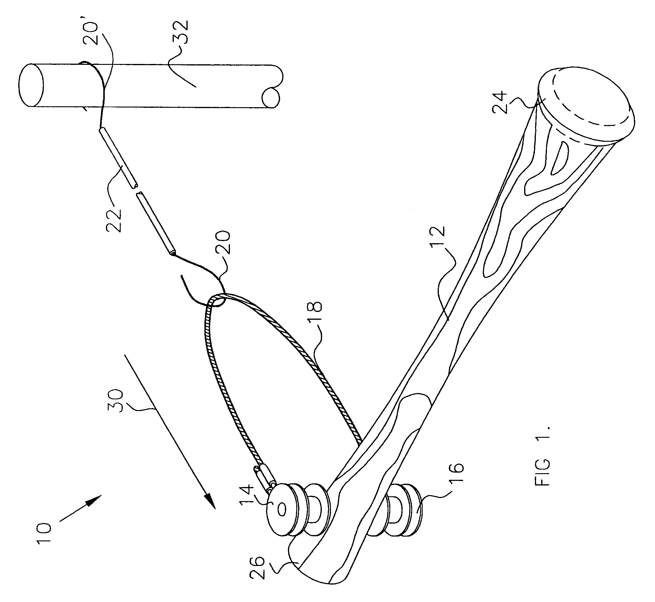
[0029]Referring now to the drawings, wherein like numerals refer to like and corresponding parts throughout the several views, in FIGS. 1, 2, 3 and 4, the invention is designated overall by the numeral 10. Bat 12 has a proximal end 24 and a distal end 26. Swivel attachment points 14 and 16 connect yoke 18 to bat 12. The swivel attachment points 14 and 16 are each formed of washers 30 and spacers 31 mounted on shaft 35 to hold the yoke ends 32 in a rotatable position on shaft 33. The assembly of spacers and washers is fixed with a cotter pin 36. In a first embodiment, the Yoke ends 38 were formed in a loop and fastened with fasteners 34.

[0030]Hooks 20 and 20′, attached at each end of cord 22, connect to fixed anchor 32, providing inertial force against the rotation of bat 12 in the direction of arrow 30.

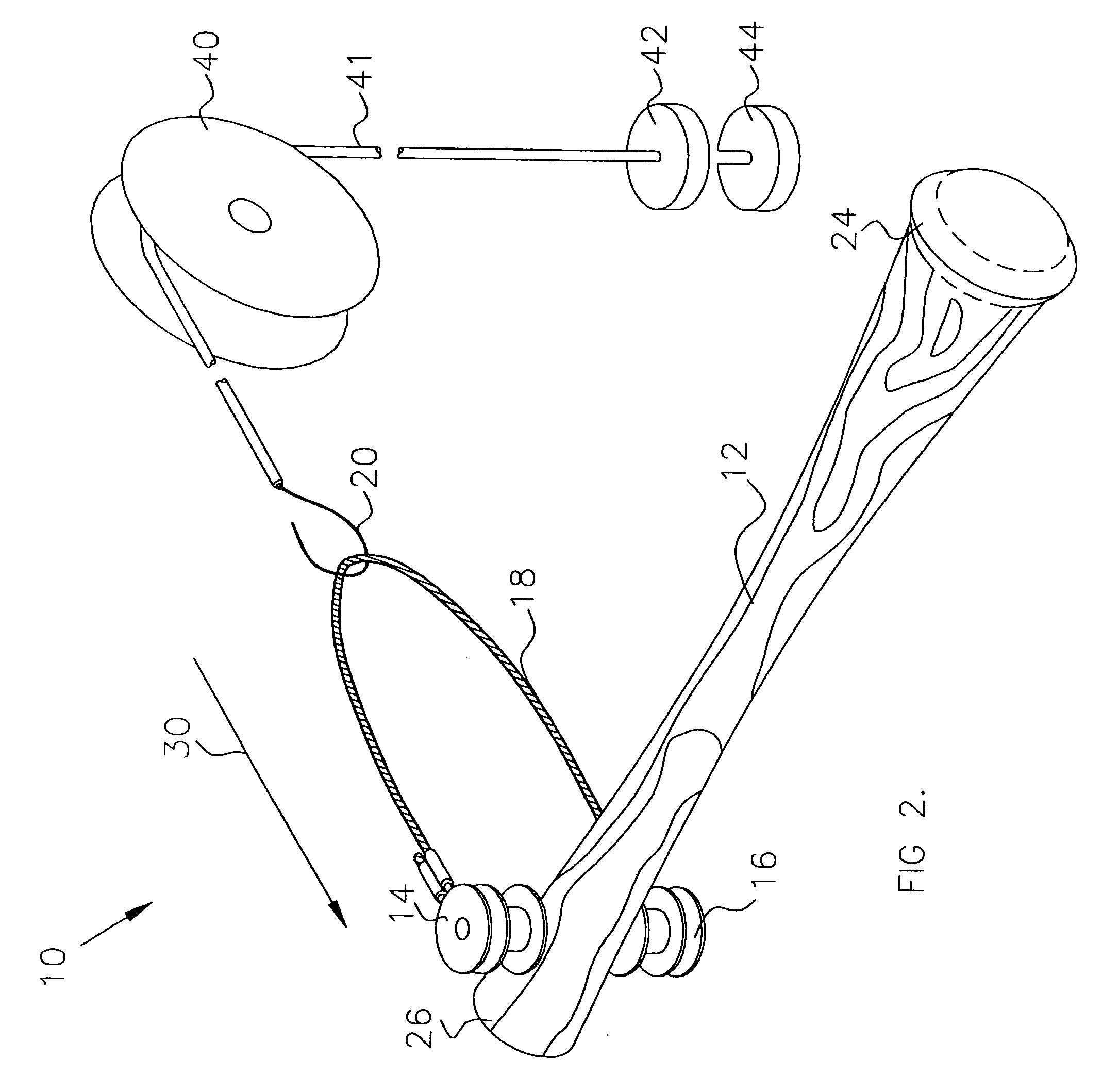
[0031]Referring to FIG. 2, in an alternative embodiment, base weights 42 and supplemental weight 44 apply tension to cord 41 and inertial force against the rotation of bat 12 in the d...

third embodiment

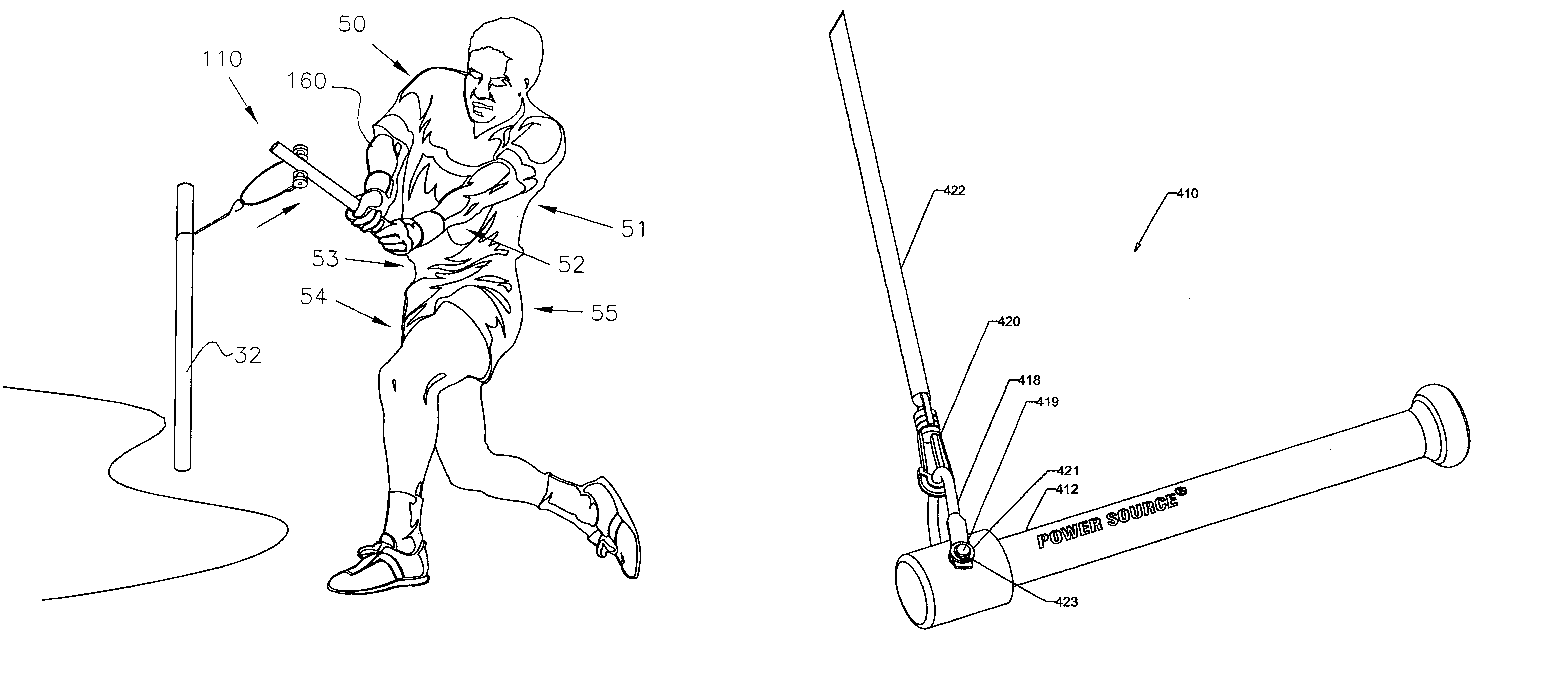
[0035]In FIGS. 14–16, the invention is designated overall by the numeral 410. The truncated training bat 412 is shown having a reinforced end 413 and a mounting hole 424. A yoke 418 is attached to the bat 424 with a yoke pin 419 which is inserted into hole 424. The yoke 418 is assembled on reinforced end 413 with spacers 421 located on pin 419 between end 413 and the ends of the yoke 418. A third spacer 421 is located between the end of the yoke 418 and the attachment clip 423. The clip 423 may be a “C” clip which can be easily mounted on, or removed, from pin 419.

[0036]The resistance tube 422 contains an attachment clip 420 mounted on each end for fastening to the yoke 418 at a first end and a second end to a fixed anchor 32 as shown in FIG. 1. The resistance tube 422 may be a section of hollow rubber tubing such as surgical tubing or elastic cord.

[0037]The yoke 418, the reinforced end 413, and the assembly of the spacers 421 and clip 423 may also be attached to the previously desc...


PUM


Abstract

The power swing training device of the invention is a tethered, truncated, training device attached by flexible elastic to a fixed anchor point, or to a pulley and weight system. A swivel attachment is attached to the distal end of the training device and a yoke is attached to the swivel attachment, and an elastic cord is attached to the yoke at one end and to a fixed point at the other. In a second embodiment, a cord is hung on a pulley attached to an anchor and a weight is placed at the other end.

Description

RELATED INVENTIONS[0001]The instant invention is a Continuation of Ser. No. 10 / 087,284, Filed Mar. 1, 2002 now U.S. Pat. No. 6,572,497 and U.S. Ser. No. 10 / 187,243 filed Jul. 2, 2002, now U.S. Pat. No. 6,592,474, Issued Jul. 15, 2003.BACKGROUND OF THE INVENTION[0002]The present invention relates to sports training devices and more particularly to a tethered training bat or other sports equipment attached by flexible elastic to a fixed anchor point, or to a pulley and weight system.DESCRIPTION OF THE PRIOR ART[0003]Prior art training bat devices are designed to accomplish one of the two basic purposes, to train a batter's muscles to swing the bat correctly, to develop the batter's muscles and improve batting strength and velocity. General batting practice using a pitcher or a pitching machine is sometimes inefficient particularly with newer players who may be unable to hit the ball. In this case, the batter gets little accuracy or muscle strength training. A pitching machine is a goo...

Claims


Application Information

Patent Timeline
Patent Type & Authority Patents(United States)
IPC IPC(8): A63B69/00A63B15/00A63B21/055A63B69/36A63B69/38
CPCA63B21/0552A63B69/0002A63B69/0026A63B21/154A63B15/00A63B21/0442A63B21/0555A63B21/0557A63B2208/0204A63B69/3623A63B69/38A63B2069/0008
Inventor HALSWORTH, ROBERT M.
Owner HALSWORTH ROBERT M
Why Eureka
Try Eureka