Braking force generator for a hydraulic vehicle brake system and vehicle brake system

a technology for hydraulic vehicles and brake systems, applied in brake systems, foot actuation initiations, transportation and packaging, etc., can solve the problems of impaired braking behaviour, affecting the hydraulic effect of drivers, and now considered discomfort, and achieves simple and inexpensive structure. , the effect of high reliability

Inactive Publication Date: 2006-03-02
LUCAS AUTOMOTIVE GMBH
View PDF8 Cites 15 Cited by
  • Summary
  • Abstract
  • Description
  • Claims
  • Application Information

AI Technical Summary

Benefits of technology

[0008] An object of the present invention is to provide a braking-force generator, of the type designated at the outset, which has a high reliab

Problems solved by technology

A disadvantage of these braking systems is that, through his actuating action on the brake pedal, the driver influences the hydraulic pressure on the wheel brakes in each case.
This is unproblematic as long as this supports the braking situation.
As soon as the driver reacts incorrectly to the actual braking situation, however, for example by injecting too much or too little braking pressure, the braking behaviour, particularly the brake travel and the directional stability, of the vehicle may be impaired, which, in the worst case, may result in an accident.
Furthermore, it is now also considered to be a matter of discomfort if the driver is aware of the action of the vehicle feedback-control system on the brake peda

Method used


Image

  • Braking force generator for a hydraulic vehicle brake system and vehicle brake system
  • Braking force generator for a hydraulic vehicle brake system and vehicle brake system
  • Braking force generator for a hydraulic vehicle brake system and vehicle brake system

Examples


Embodiment Construction

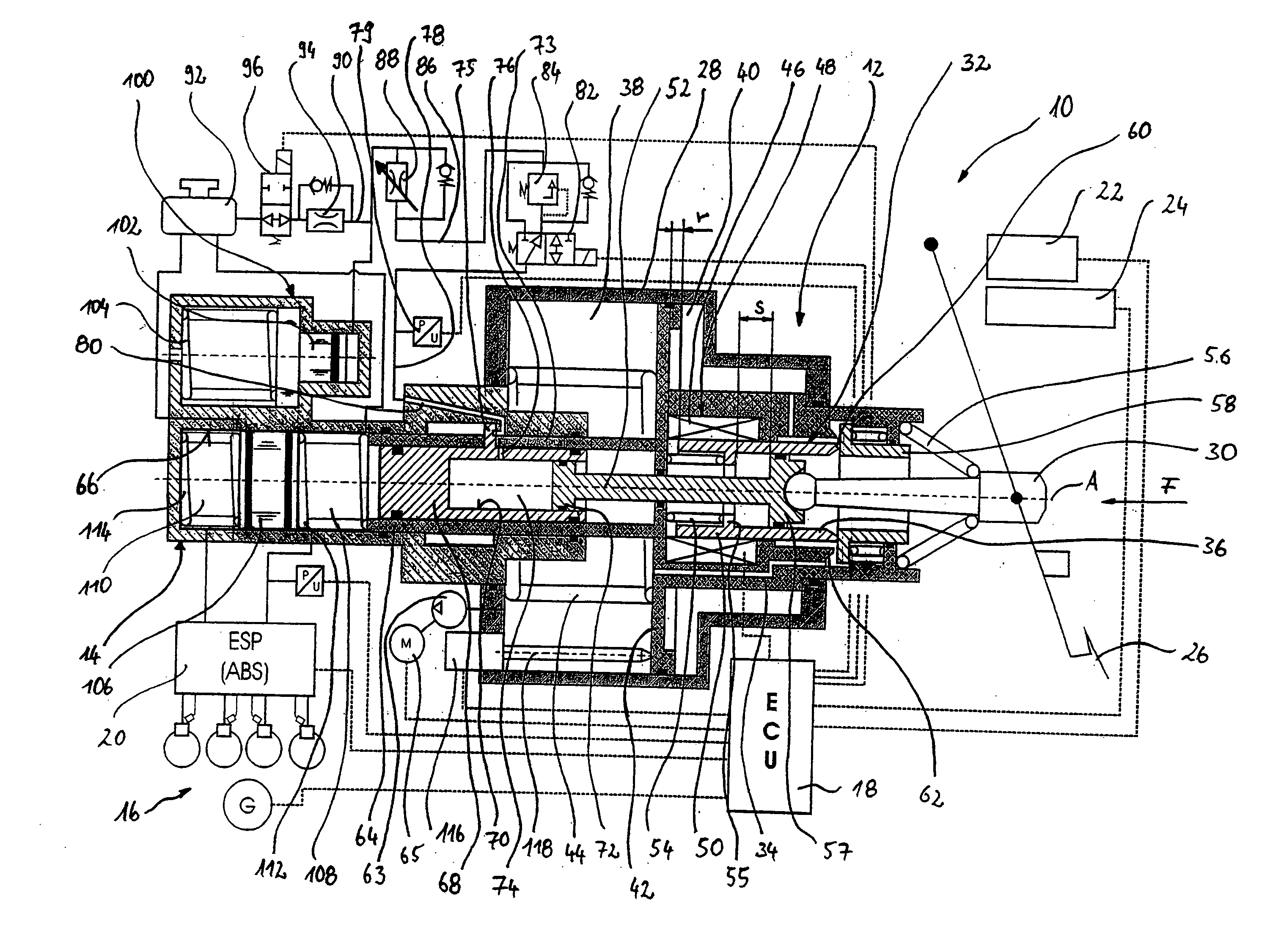
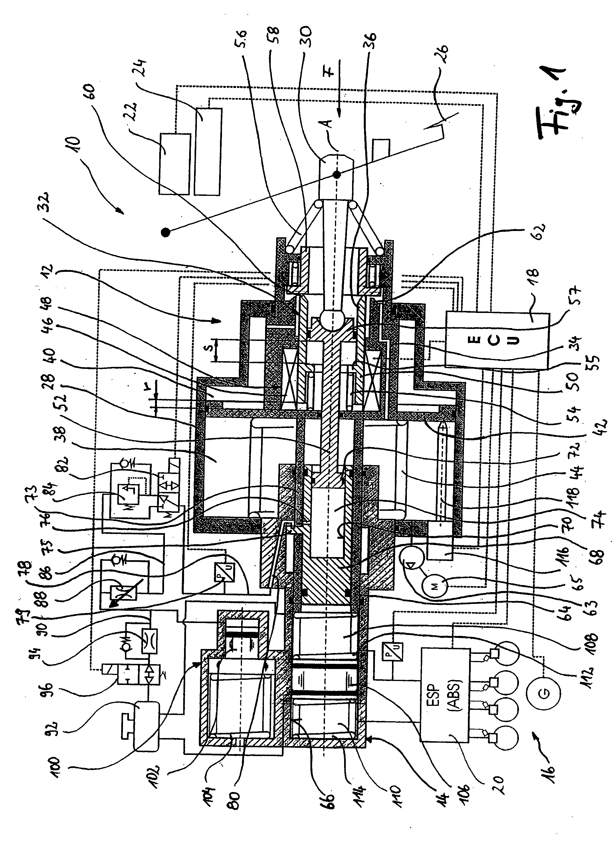
[0024] In FIG. 1, a braking system according to the invention is represented schematically and denoted generally by the reference 10. This braking system comprises a braking-force generator 12, and a master brake cylinder 14 which is coupled to the latter. The master brake cylinder 14 communicates, in conventional manner, with a braking system 16, which controls via an electronic control unit 18. In this case, the electronic control unit 18 receives signals from various feedback-control systems within the vehicle, such as, for example, an electronic stability program and an anti-lock system 20, an automatic cruise control system 22 or the like. The signals flowing from these programs to the electronic control unit 18 are evaluated and used for activating the braking-force generator 12 according to the invention. In addition, the electronic control unit 18 receives signals from a rotational-angle sensor 24, which detects the current position of a brake pedal 36 and thereby provides a...


PUM


Abstract

The invention relates to a braking-force generator for a hydraulic vehicle braking system, comprising a force input element which can be coupled, or is coupled, to a brake pedal and is displaceable in a basic casing of the braking-force generator, a master brake cylinder, in which a primary piston is displaceably guided, the primary piston delimiting, with the master brake cylinder, a primary pressure chamber for generating a hydraulic braking pressure, a pedal-counterforce simulation means that can be coupled to the force input element, a pedal-actuation detection means for detecting a pedal actuation, and an actuating-force generation means for exerting an actuating force on the primary piston. In the case of this braking-force generator, provision is made whereby the pedal-counterforce simulation means can be coupled to the force input element via a hydraulic system, the hydraulic system being realized with a throttle valve which is provided in the hydraulic connection to the pedal-counterforce simulation means and can be optionally switched into different throttle valve positions.

Description

CROSS-REFERENCE TO RELATED APPLICATIONS [0001] This application claims priority to German Patent Application No. 10 2004 041 924.8 filed Aug. 30, 2004, the disclosures of which are incorporated herein by reference. BACKGROUND OF THE INVENTION [0002] The present invention relates to a braking-force generator for a hydraulic vehicle braking system, comprising a force input element which can be coupled, or is coupled, to a brake pedal and is displaceable in a basic casing of the braking-force generator, a master brake cylinder, in which a primary piston is displaceably guided, the primary piston delimiting, with the master brake cylinder, a primary pressure chamber for generating a hydraulic braking pressure, a pedal-counterforce simulation means that can be coupled to the force input element, a pedal-actuation detection means for detecting a pedal actuation, and an actuating-force generation means for exerting an actuating force on the primary piston. [0003] In the case of currently c...

Claims


Application Information

Patent Timeline
IPC IPC(8): B60T8/34B60T7/04B60T8/40B60T13/72
CPCB60T13/72B60T8/4077
Inventor SCHLUTER, PETER
Owner LUCAS AUTOMOTIVE GMBH
Why Eureka
Try Eureka