Method of manufacturing an internal antenna, and antenna element

Inactive Publication Date: 2005-09-27
PULSE FINLAND
View PDF18 Cites 65 Cited by
  • Summary
  • Abstract
  • Description
  • Claims
  • Application Information

AI Technical Summary

Benefits of technology

[0007]An advantage of the invention is that the manufacturing costs of an antenna element are relatively low. This is a consequence of the fact that the elements can be fabricated using a relatively small number of work stages. Another advantage of the invention is that the radio frequency characteristics of an element according to the invention are good as there are no metallic junctions

Problems solved by technology

For example, in a high-frequency antenna, even a slight mechanical change may render the whole device unusable.
As far as antennas are concerned, protruding antennas,

Method used


Image

  • Method of manufacturing an internal antenna, and antenna element
  • Method of manufacturing an internal antenna, and antenna element
  • Method of manufacturing an internal antenna, and antenna element

Examples


Embodiment Construction

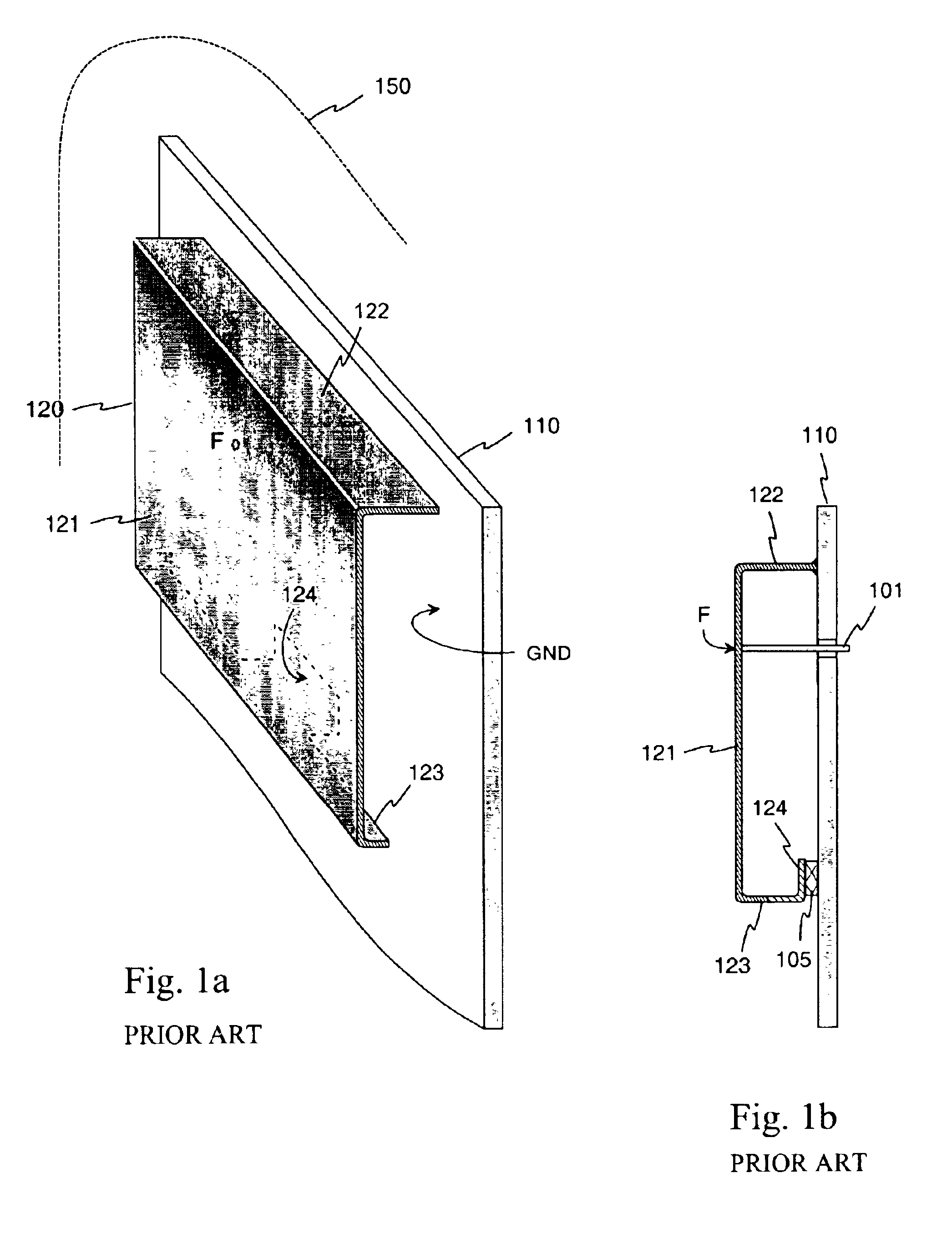
[0017]FIG. 1 was already discussed in conjunction with the description of the prior art.

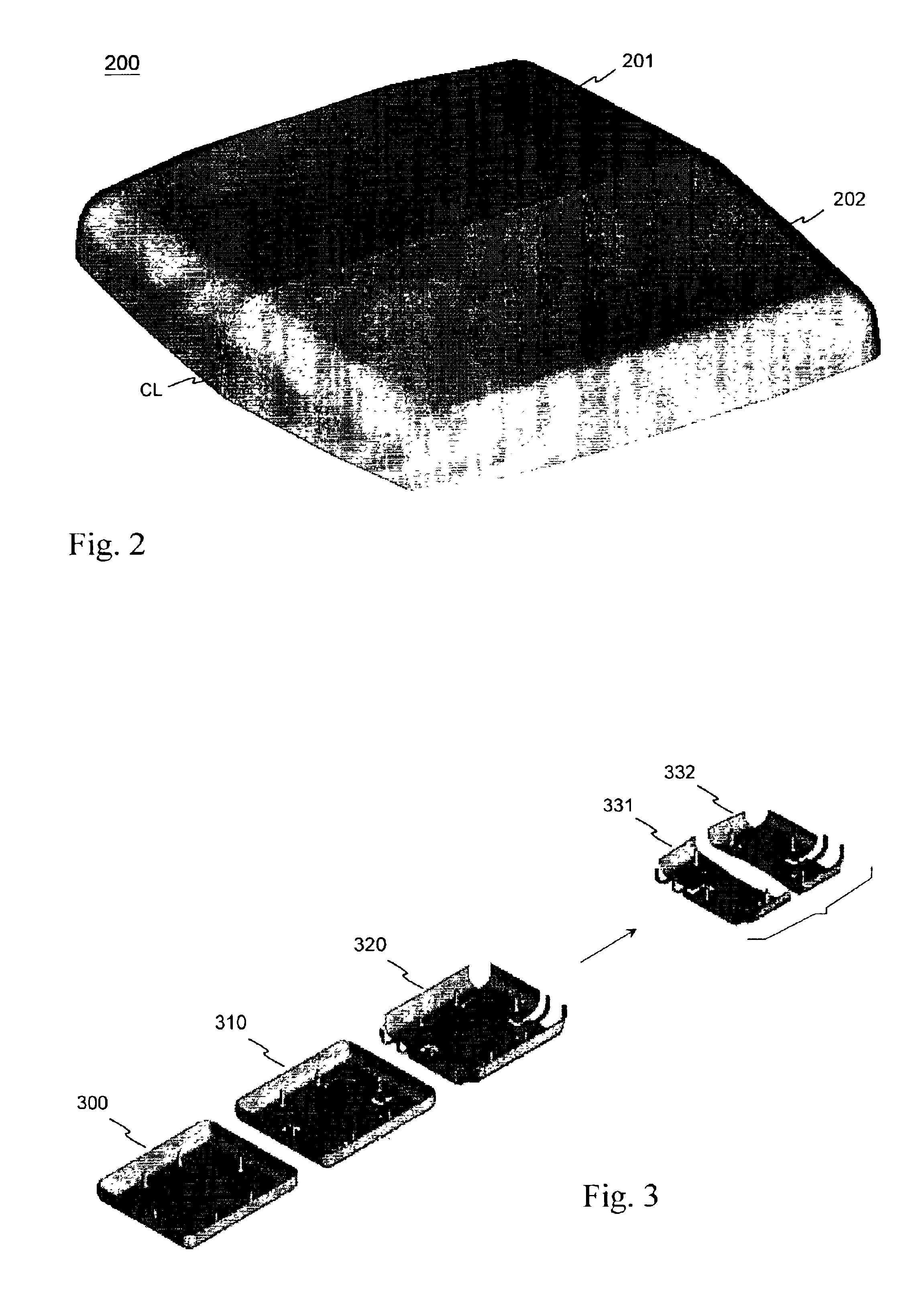
[0018]FIG. 2 shows an example of an antenna billet according to the invention viewed from above. An antenna billet means in this description and in the claims a piece extruded from a basic billet, having at least one antenna element-shaped part. The single-piece antenna billet 200 comprises a first half 201 and a second half 202 separated by a center line CL marked in broken line in the example depicted in FIG. 2. The halves are identical in form and composition and are located symmetrically in the antenna billet. Such a symmetrical structure of an extrusion piece is advantageous as regards the extrusion process. The edges of the antenna billet 200 are curved so that the shape of the outer surfaces of the halves conforms to the shape of the inner surface of the covering of the radio device in which the antenna is to be placed.

[0019]FIG. 3 shows an example of manufacturing stages of antennas accor...


PUM


Abstract

The invention relates to a method of manufacturing a structure suitable as an internal antenna in small radio devices, and an antenna element to which the method is applied. The antenna element comprises a radiating plane and additionally e.g. supportive elements, a feed conductor and short-circuit conductor as well as extensions to increase capacitance. The antenna element is fabricated by first extruding from a billet an antenna billet, and working the latter as required. The antenna billet may be symmetrical so that two antenna elements will be produced when it is cut in half. Advantageously the antenna element is fabricated so as to conform with the covering of the device in which it is placed. It may also be part of a covering of a device. The manufacturing costs of the antenna element are relatively low and the radio characteristics of the element are good. An antenna structure employing the element has got few separate parts and is mechanically firm and space-conserving.

Description

FIELD OF INVENTION[0001]The invention relates to a method of manufacturing a structure suitable as an internal antenna especially in small radio devices. Furthermore the invention relates to an antenna element resulting from the application of the method.BACKGROUND OF THE INVENTION[0002]Manufacturing costs of apparatuses in general and mass products in particular should be as low as possible. The less there are parts in a structure and work stages in manufacturing the parts, the lower the costs. Furthermore, in portable radio devices, the mechanical stability of a structure is emphasized. For example, in a high-frequency antenna, even a slight mechanical change may render the whole device unusable. The less there are parts in a structure and the sturdier and better protected the parts, the better the stability and, hence, the reliability of the structure. So, a low count of parts helps both minimize the manufacturing costs and improve the reliability of a device.[0003]As far as ante...

Claims


Application Information

Patent Timeline
IPC IPC(8): H01Q5/00H01Q9/04H01Q1/24H01Q5/371
CPCH01Q1/243H01Q5/371H01Q9/0442H01Q9/0421
Inventor BORDI, MIKAANNAMAA, PETTERIMIKKONEN, ESARAATIKAINEN, SEPPO
Owner PULSE FINLAND
Why Eureka
Try Eureka