Method and apparatus for event management in a disk drive

Inactive Publication Date: 2005-09-27
KK TOSHIBA
View PDF12 Cites 16 Cited by
  • Summary
  • Abstract
  • Description
  • Claims
  • Application Information

AI Technical Summary

Problems solved by technology

However, the host system can recognize an error occurring timing only...

Method used


Image

  • Method and apparatus for event management in a disk drive
  • Method and apparatus for event management in a disk drive
  • Method and apparatus for event management in a disk drive

Examples


first embodiment

(First Embodiment)

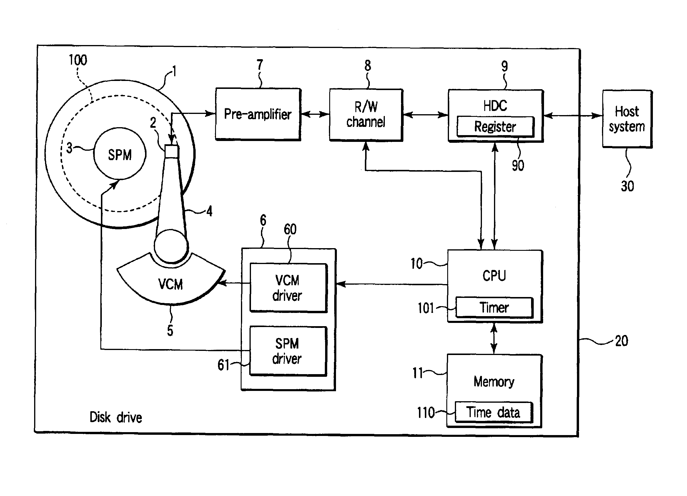
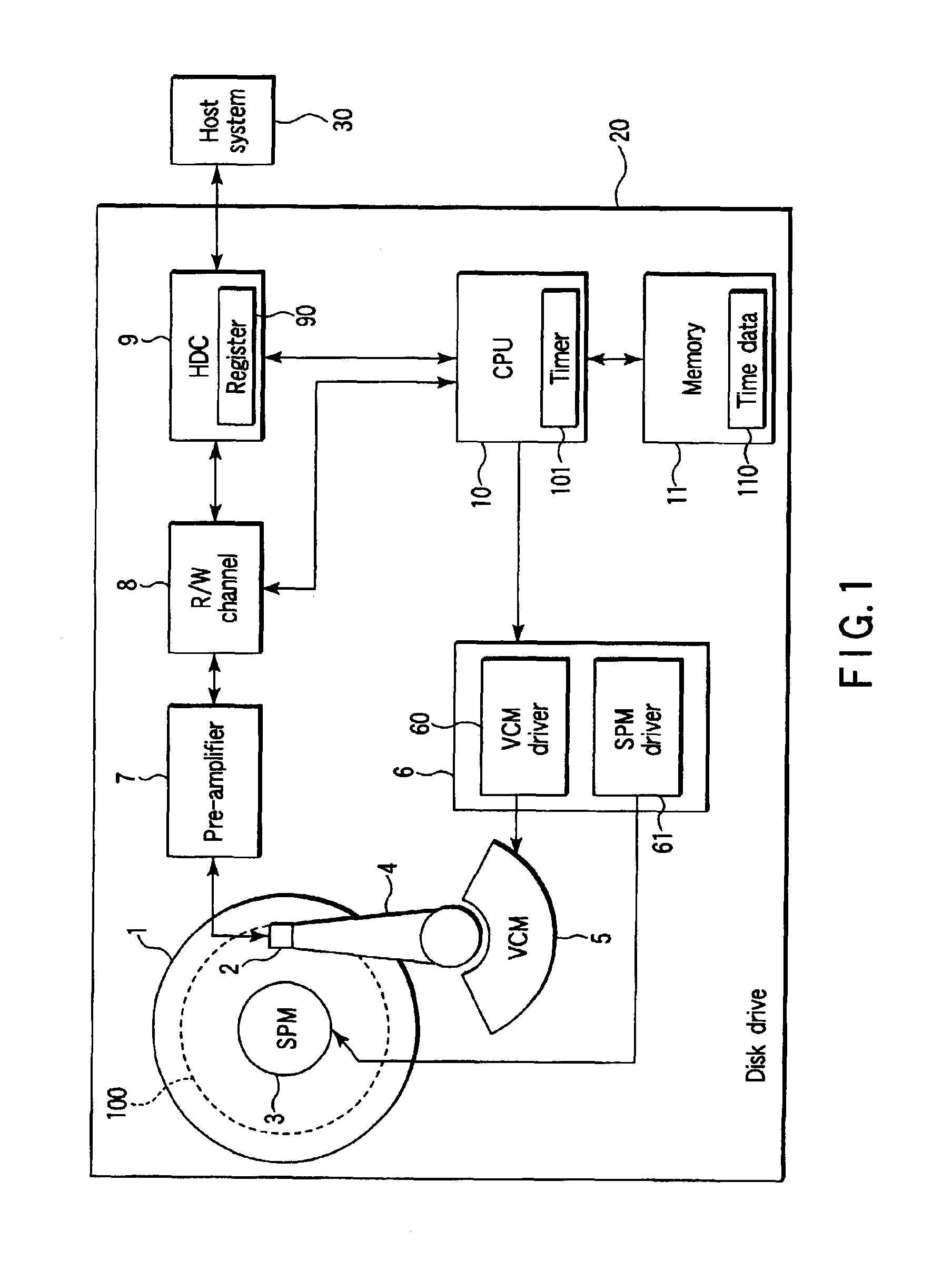
[0022]FIG. 1 is a block diagram showing a major section of a disk drive 20 relating to the present invention.

[0023]A present disk driver 20 comprises a hard disk drive (HDD) using a magnetic disk medium 1 as a data recording medium 1. The disk drive medium 1 is mounted on a spindle motor (SPM) 3 and configured to be rotated at high speed. On the disk medium 1, many tracks are formed as a data recording area.

[0024]A few tracks on the outermost peripheral side of the disk medium 1 are used as a system area 100 for recording data other than normal user data. As will be set out below, various kinds of management information, such as error log information (error log file) and turned-ON time information, are recorded on the system area 100.

[0025]The present disk drive 20 has a magnetic head 2 for performing a data read / write operation on a disk medium 1. The magnetic head 2 is mounted on an actuator 4. The actuator 4 is moved, under control, over the disk medium 1 in a r...

second embodiment

(Second Embodiment)

[0053]FIG. 7 is a flowchart relating to a second embodiment. The second embodiment is supposed to have a disk drive 20 of a structure as shown in FIG. 1.

[0054]First, a disk drive 20 measures a turned-ON time from a power ON time to a power OFF time and allows the turned-ON time data to be recorded on a system area of a disk medium 1. In this case, a CPU 10 additively integrates a current turned-ON time to a past turned-ON time as an integrating value and records corresponding turned-ON time data. In a normal situation, the turned-ON time data corresponds to an integrated value from the shipping of the drive 20 to a current turned-ON time.

[0055]With reference to FIG. 7, the present embodiment will be explained in more detail below in connection with the disk medium drive 20 having such a function.

[0056]At a power ON time, an HDC 9 of the disk medium drive 20 receives time data 110 sent from a host system 30—step S20. The CPU 10 allows time data 110 which is receive...


PUM


Abstract

A disk drive is disclosed which has an event management function. At an event occurring time such as an error generation, the disk drive records the event information together with time data. A CPU of the disk drive is configured to, at a power ON time, allow the time data which is received from a host system to be stored in a memory. At the time of an error occurring, the CPU, while using the time measured by an internal timer and time data, generates time data which is synchronized with the internal time of the host system.

Description

CROSS-REFERENCE TO RELATED APPLICATIONS[0001]This application is based upon and claims the benefit of priority from the prior Japanese Patent Application No. 2002-189941, filed Jun. 28, 2002, the entire contents of which are incorporated herein by reference.BACKGROUND OF THE INVENTION[0002]1. Field of the Invention[0003]The present invention relates generally to the field of disk drives and, in particular, to an event management technique using time information.[0004]2. Description of the Related Art[0005]Generally, a typical hard disk drive has a built-in function to detect an error as one of the events occurring in a read / write operation, etc., and record the error information.[0006]In general, in the disk drive, error log information (error log file) including various kinds of error information is stored in a system area on a disk medium serving as a recording medium. The system area comprises, for example, a recording area corresponding to a few tracks on the outermost periphera...

Claims


Application Information

Patent Timeline
IPC IPC(8): G11B27/36G06F11/34G06F3/06
CPCG11B27/36
Inventor IMAI, HIROSHI
Owner KK TOSHIBA
Why Eureka
Try Eureka