Right perspective drawing tool

Inactive Publication Date: 2005-10-04
ROSETTI ELIZABETH
View PDF12 Cites 10 Cited by
  • Summary
  • Abstract
  • Description
  • Claims
  • Application Information

AI Technical Summary

Benefits of technology

[0007]The Right Perspective Drawing Tool uses a modified tape measure with a suction cup inserted in the bottom wall of the tape measure housing to form a single unit. There is a round hole in the bottom wall of the tape measure housing at center. The domed-top of the suction cup is held within the tape measure housing and the neck of the suction cup fits a round hole made to accommodate its size and allow movement but the hole is smaller than the domed-top. The user can press down on the unit to suction it on a flat drawing service like a tabletop and it will swivel at the neck area of the suction cup 360 degrees. This will enable the user to position the tool on an established vanishing point by engaging the pivotal suction cup and, with the tape extended and locked, use the edge of the tape like a straight edge to draw a line. The user can then draw all horizontal lines on the side of a building that converge on the established vanishing point quickly and accurately by slightly moving the tape, up or down, pivoting off the suction cup.
[0009]The object of the invention is to give the user the opportunity to anchor the unit to a stationary point on a flat surface and not worry about it moving. This allows the user to concentrate on drawing a line accurately and then pivoting the tape slightly off the same point to draw the next line in the design.

Problems solved by technology

The user would then draw the line with the possibility of the straightedge moving off the vanishing point because there was nothing to secure it or keep it from moving while the user drew the line at the far end of the straightedge.

Method used


Image

  • Right perspective drawing tool
  • Right perspective drawing tool

Examples


Embodiment Construction

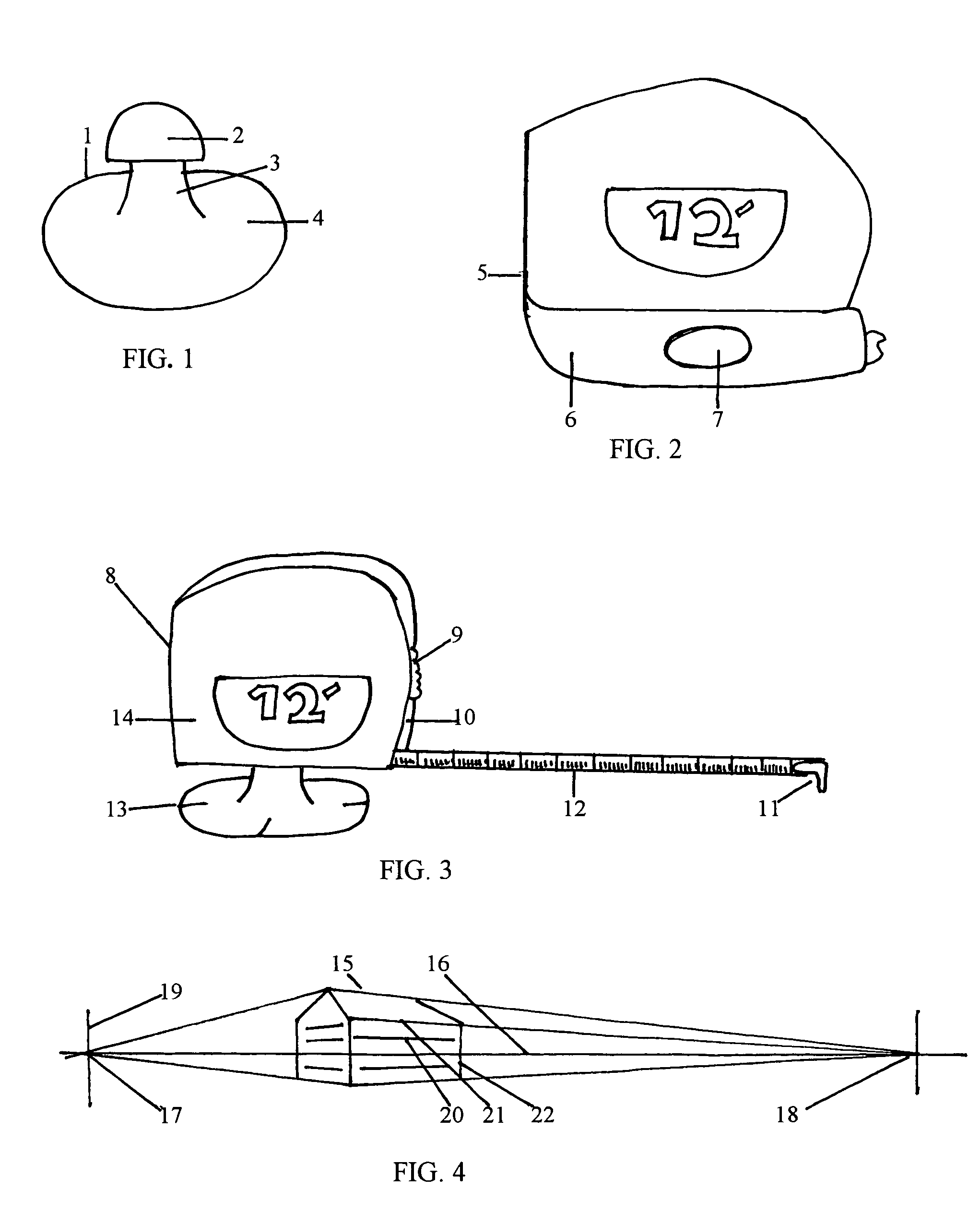
[0014]FIG. 1 is a drawing of a typical suction cup 1 with a domed-top 2 and a neck 3, both of which protrude upward form the center of the concave base 4.

[0015]FIG. 2 is a drawing of a tape measure housing 5, with a view of the bottom wall 6 of the tape measure housing 5, and a round hole 7 in the center of the bottom wall 6 of the tape measure housing 5.

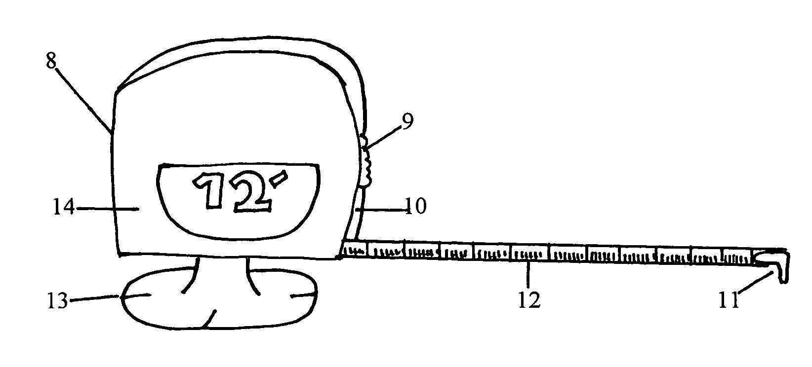
[0016]FIG. 3 is a drawing of The Right Perspective Drawing Tool 8 assembled with both tape measure housing and suction cup. It shows a locking mechanism 9 on front wall 10 of tape measure housing 5, tape tip 11 on end of the steel tape 12, cross hair marking sets 13 on the concave base 4 of suction cup 1 and side wall 14.

[0017]FIG. 4 is a drawing of a house 15 as an example of what a drawing would look like using The Right Perspective Drawing Tool. It defines terms used to describe points and lines necessary to make perspective drawings. The drawing shows a line representing the horizon line 16, a left vanishing point 17, and a righ...


PUM


Abstract

The Right Perspective Drawing Tool invention consist of a typical tape measure with a housing enclosing a retractable coiled tape, tape tip, and locking mechanism with a suction cup attached to the bottom of the unit. The domed-top of the suction cup is inside the housing and the neck fits a hole in the bottom of the housing allowing the unit to swivel 360 degrees and suction onto a flat surface. This unit will allow students or professionals to draw the illusion of a building having a three-dimensional, realistic contour. What is new in the art to which this invention pertains is that the user can position the unit on a single point and draw all lines pivoting off the same point, like rows of bricks or siding, by simply sliding the tape up or down.

Description

CROSS-REFERENCE TO RELATED APPLICATIONS[0001]Not ApplicableSTATEMENT REGARDING FEDERALLY SPONSORED RESEARCH OR DEVELOPMENT[0002]Not applicableREFERENCE TO SEQUENCE LISTING, A TABLE, OR A COMPUTER PROGRAM LISTING COMPACT DISK APPENDIX[0003]Not ApplicableBACKGROUND OF THE INVENTION[0004]The field of endeavor to which this invention pertains as paraphrased by the applicable U.S. patent Classification definitions or the subject matter of the claimed invention is under Class 33, Geometrical Instruments and 18.3, Perspective Drawing Tools identified under subclass 18.1.[0005]The Right Perspective Drawing Tool, consisting of a typical tape measure with a suction cup added to the bottom of the housing, was invented to help any student or professional involved with representational drawing and perspective view drawing. This includes a wide variety of fields such as Illustration, Interior Design, Architecture, and Fine Arts. Each of these areas applies perspective techniques for different pur...

Claims


Application Information

Patent Timeline
Patent Type & Authority Patents(United States)
IPC IPC(8): B43L9/00B43L9/04G01B3/10G01B3/02B43L13/14B43L13/16
CPCB43L13/14B43L13/16G01B3/1041G01B3/1071G01B2003/1046G01B2003/1074G01B3/1046
Inventor ROSETTI, ELIZABETH
Owner ROSETTI ELIZABETH
Why Eureka
Try Eureka