Hay saver insert

a technology of inserts and hay, which is applied in the field of hay saver inserts, can solve the problems of considerable hay waste, and achieve the effect of preventing hay waste and preventing spoilage of hay

Inactive Publication Date: 2005-10-04
PLYMOUTH INDS
View PDF2 Cites 33 Cited by
  • Summary
  • Abstract
  • Description
  • Claims
  • Application Information

AI Technical Summary

Benefits of technology

[0008]Yet another object of the invention is to provide an insert for a conventional bale feeder which prevents hay waste.
[0009]Yet another object of the invention is to provide an insert for a conventional round hay feeder which prevents spoilage of the hay therein by keeping the hay off the ground.

Problems solved by technology

A large amount of hay is pulled outwardly through the bars by the animals with the excess hay falling onto the ground and being trampled by the livestock thereby resulting in considerable waste of the hay.

Method used


Image

  • Hay saver insert
  • Hay saver insert
  • Hay saver insert

Examples


Embodiment Construction

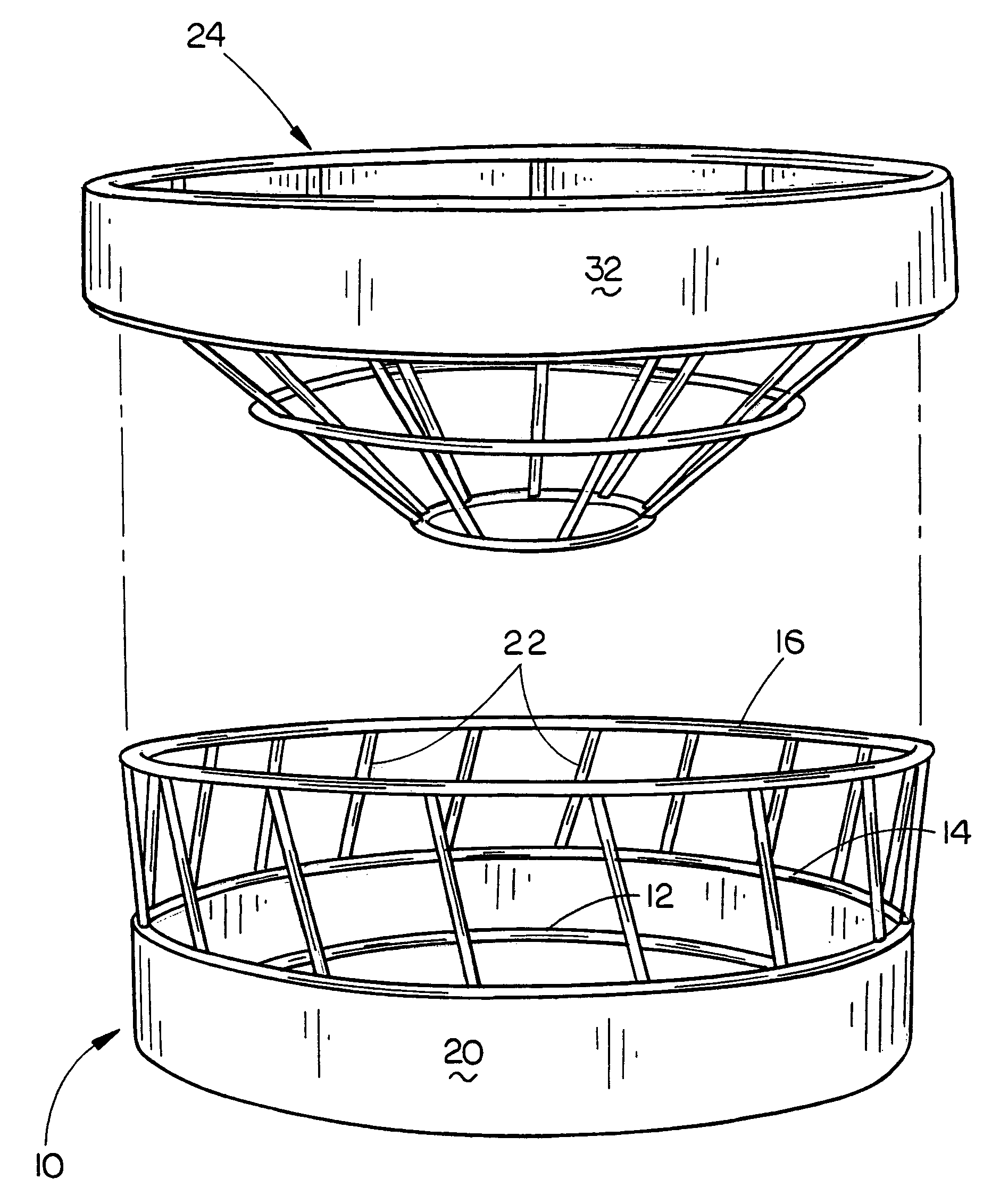
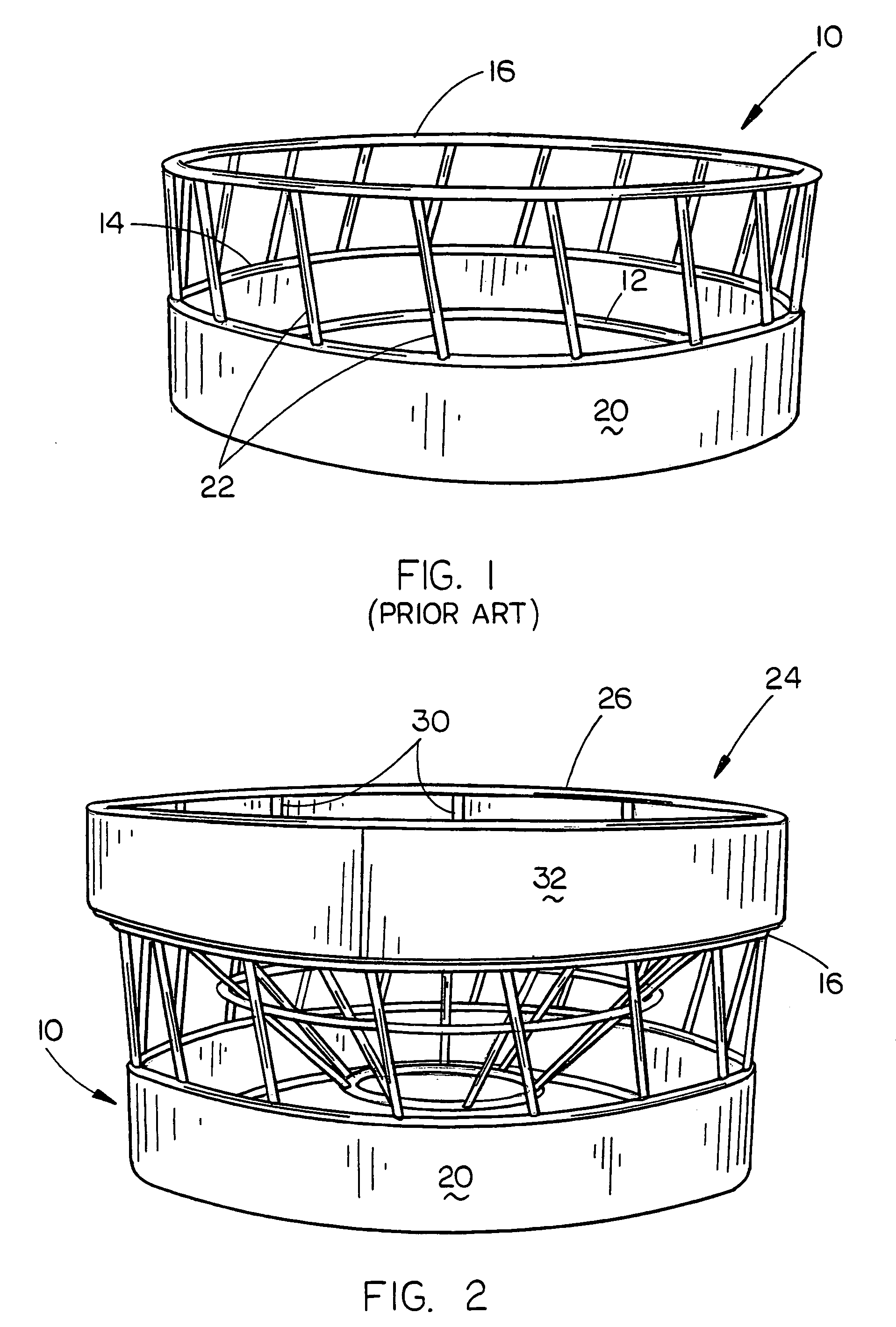
[0018]In the drawings, the numeral 10 refers to a conventional livestock feeder which is used to feed cylindrical hay bales placed therein to livestock. The bale feeders of the prior art are generally cylindrical or round and include a lower ring-shaped frame member 12, an intermediate ring-shaped frame member 14, and an upper ring-shaped frame member 16. In some feeders, the intermediate ring-shaped frame member 14 is omitted. In many prior art feeders, a plurality of horizontally spaced-apart bars or pipes are welded to and extend between the frame members 12 and 14. The bars are normally covered or enclosed by a shield 20 which is secured to frame members 12 and 14 and which extends therebetween to prevent hay from passing outwardly through the bars.

[0019]A plurality of spaced-apart bars or pipes 22 are welded to and extend between the frame members 14 and 16 in conventional fashion. Normally, the bars 22 are angularly disposed. The pipes 22 are sufficiently spaced-apart to permi...


PUM


Abstract

A hay saver insert is adapted to be removably positioned on and within a conventional cylindrical hay feeder. The insert includes an upper end portion which rests upon the upper end of the conventional feeder and a conical-shaped portion which extends downwardly into the interior of the feeder. Hay is placed within the insert and the animals have access thereto. Hay being pulled from the insert by the animals may fall into the area between the conical-shaped portion of the insert and the interior of the feeder which prevents the hay from being trampled.

Description

CROSS-REFERENCE TO RELATED APPLICATIONS[0001]This is a continuation application of Petitioner's earlier application Ser. No. 10 / 683,738 filed Oct. 13, 2003, now U.S. Pat. No. 6,789,505 entitled A HAY SAVER INSERT which is a continuation application of Petitioner's earlier application Ser. No. 10 / 384,879 filed Mar. 5, 2003, entitled A HAY SAVER INSERT, now U.S. Pat. No. 6,672,247.BACKGROUND OF THE INVENTION[0002]1. Field of the Invention[0003]This invention relates to a hay saver insert and more particularly to a hay saver insert which is inserted into a conventional round or cylindrical bale feeder.[0004]2. Description of the Related Art[0005]Conventional round or cylindrical feeders have been used for many years to feed large round roll-type bales to livestock. Most conventional round bale feeders include a circular metal frame having a plurality of horizontally spaced-apart bars or pipes positioned thereon which enable the animals to insert their heads therethrough to gain access ...

Claims


Application Information

Patent Timeline
Patent Type & Authority Patents(United States)
IPC IPC(8): A01K1/00A01K1/10A01K5/00A01K5/01
CPCA01K5/01
Inventor LIENEMANN, TREVOR L.
Owner PLYMOUTH INDS
Why Eureka
Try Eureka