Electron gun for cathode ray tube

a technology of electron gun and cathode ray tube, which is applied in the direction of cathode ray tube/electron beam tube, electromagnetic effect elimination, electric discharge tube, etc., can solve the problems of deteriorating the efficiency of the magnetic field affecting the electron beam, difficult to precisely control the location of the electron beam, and difficult to displace the location of the svm coil, so as to prevent the deterioration of the focusing property and improve the efficiency of the magnetic field

Inactive Publication Date: 2005-10-04
SAMSUNG SDI CO LTD
View PDF10 Cites 4 Cited by
  • Summary
  • Abstract
  • Description
  • Claims
  • Application Information

AI Technical Summary

Benefits of technology

[0020]It is therefore an objective of the present invention to provide an electron gun that can is, prevent the deterioration of the focusing property while improving the efficiency of the magnetic field generated by the SVM coil.

Problems solved by technology

This deteriorates the magnetic field efficiency affected on the electron beams, making it difficult to precisely control the location of the electron beams.
Since the location of the SVM coil is predetermined when designing the electron gun, it is difficult to displace the location of the SVM coil.
However, when increasing the number of coil turns, the size of the SVM is increased, and when increasing the current, the energy consumption is increased.
However, an outer electric field (including an electric field generated by static electric fir charge accumulated on an inner wall of the neck portion) may be infiltrated through the gap, deteriorating the focusing operation of the focus electrode.
However, since plural metal plates are attached to each of the facing surfaces of the electrodes, the magnetic field generated by the SVM coil may be blocked by the plates, thereby generating the eddy current.
In addition, since the gap between the metal plates cannot be defined having a sufficient distance, improvement of the properties of the SVM coil is limited.
However, it is difficult to form the slit on the sidewall of the focus electrode, thereby increasing the manufacturing costs.

Method used


Image

  • Electron gun for cathode ray tube
  • Electron gun for cathode ray tube
  • Electron gun for cathode ray tube

Examples


Embodiment Construction

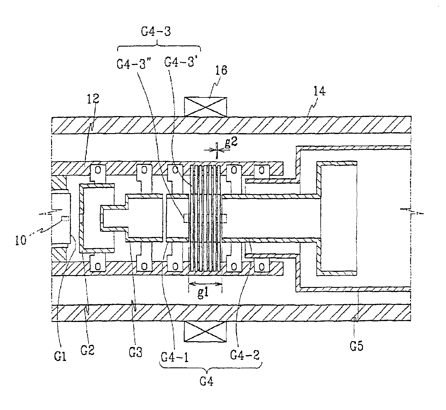
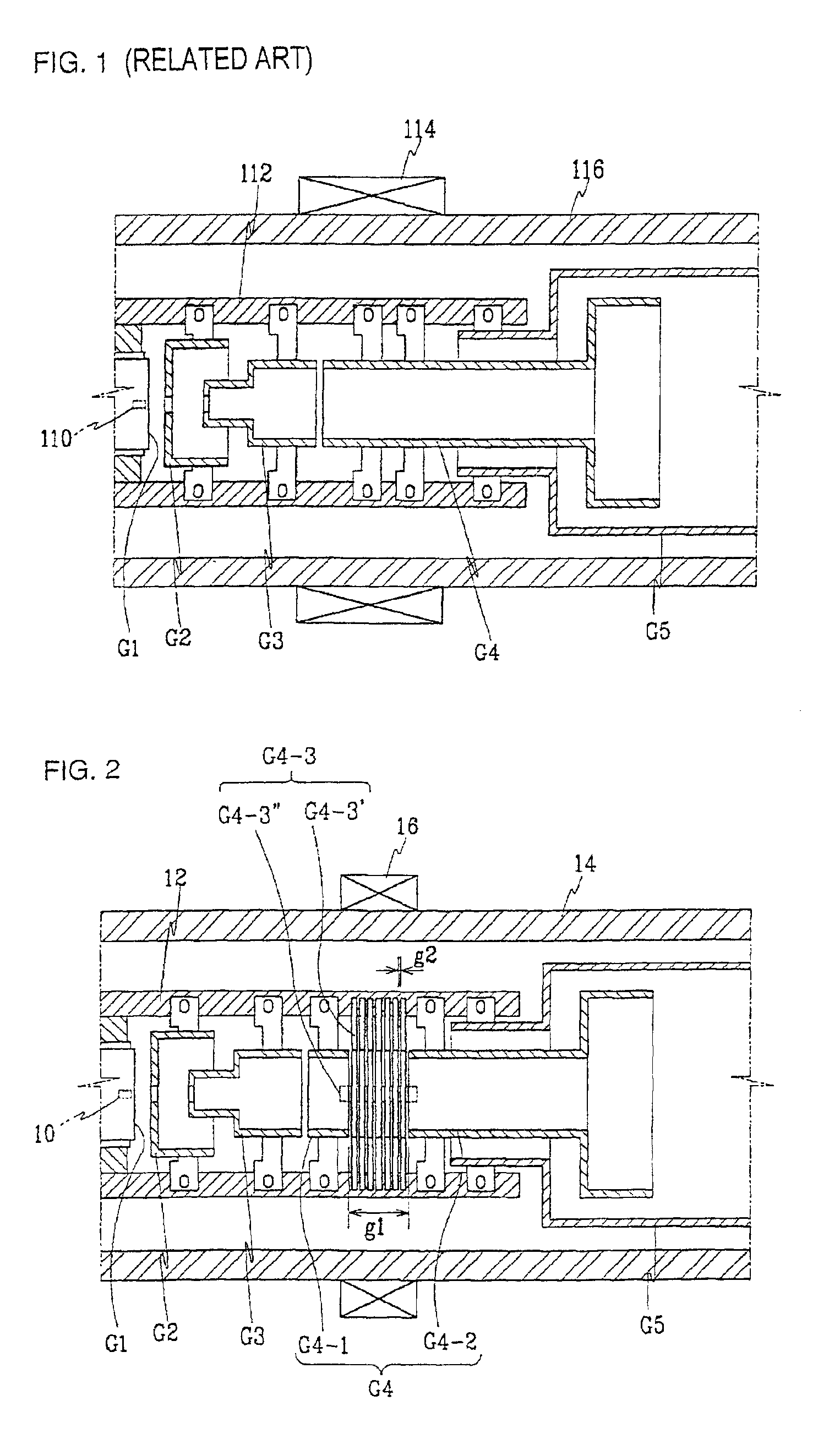
[0040]Preferred embodiments of the present invention will be described in detail with reference to the accompanying drawings. FIG. 1 shows a conventional electron gun. The electron gun depicted in FIG. 1 is one used for a high definition projection CRT. The electron gun includes a cathode 110 for radiating electrons, first to fifth grid electrodes G1-G5 for controlling the electrons radiated from the cathode 110, and a bead glass 112 for supporting the grid electrodes. The grid electrodes G1-G5 are disposed inside the neck portion.

[0041]The first and second electrodes G1 and G2 are formed as flat electrodes, and the third and fourth electrodes G3 and G4 are formed as cylindrical electrodes. The fourth electrode G4 is used as a focus electrode for focusing electron beams.

[0042]As shown in the FIG. 1, the SVM coil 114 is disposed corresponding to the fourth electrode G4 around the neck portion 116.

[0043]The cylindrical portion of the fourth electrode G4 is located corresponding to the...


PUM


Abstract

An electron gun for a cathode ray tube includes a cathode for radiating electron beams, a scanning velocity modulation coil for synchronizing the electron beams with an image signal, a focus electrode having first and second sub-electrodes disposed with a gap through which a magnetic field generated by the scanning velocity modulation coil passes, a plurality of grid electrodes with the focus electrode for controlling the electron beams radiated from the cathode, a support for aligning and supporting the grid electrodes, and a shield electrode electrically connected to the first and second sub-electrodes to protect against infiltration of an outer electric field. The shield electrode includes plural intermediate electrodes disposed in the gap between the first and second sub-electrodes, and electrical connecting unit for electrically connecting the intermediate electrodes to the first and second sub-electrodes. The intermediate electrodes are spaced away from each other.

Description

CLAIM OF PRIORITY[0001]This application makes reference to, incorporates the same herein, and claims all benefits accruing under 35 U.S.C. §119 from an application for ELECTRON GUN FOR CATHODE RAY TUBE earlier filed in the Korean Industrial Property Office on May 15, 2001 and there duly assigned Serial No. 2001-26467.BACKGROUND OF THE INVENTION[0002]1. Field of the Invention[0003]The present invention relates to a cathode ray tube (CRT), and more particularly, to an electron gun for a CRT that can improve the efficiency of the magnetic field generated by a scanning velocity modulation (SVM) coil and effectively prevent the focus deterioration caused by an outer electric field.[0004]2. Description of the Related Art[0005]Generally, a CRT has a phosphor screen scanned by electron beams, a neck portion in which an electron gun for generating the electron beams is disposed, and a funnel portion for connecting the screen and the neck portion. Disposed around the neck portion is a deflect...

Claims


Application Information

Patent Timeline
Patent Type & Authority Patents(United States)
IPC IPC(8): H01J29/48H01J29/06
CPCH01J29/06H01J29/488H01J2229/003H01J2229/5688H01J29/48
Inventor PARK, DUK-SUNGWON, YEONG-GUONJUNG, BONG-WOOKHWANG, SE-JA-CHUL
Owner SAMSUNG SDI CO LTD
Why Eureka
Try Eureka