
Method and apparatus for the distribution of ice

Inactive Publication Date: 2005-10-11
TMO ENTERPRISES
View PDF14 Cites 25 Cited by
  • Summary
  • Abstract
  • Description
  • Claims
  • Application Information

AI Technical Summary

Benefits of technology

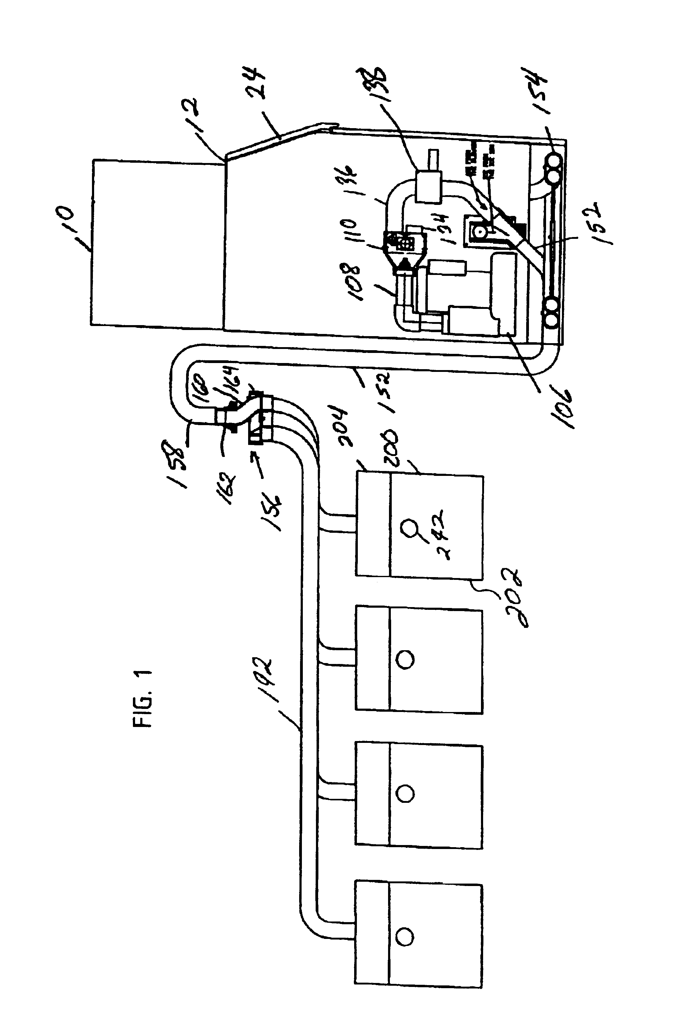
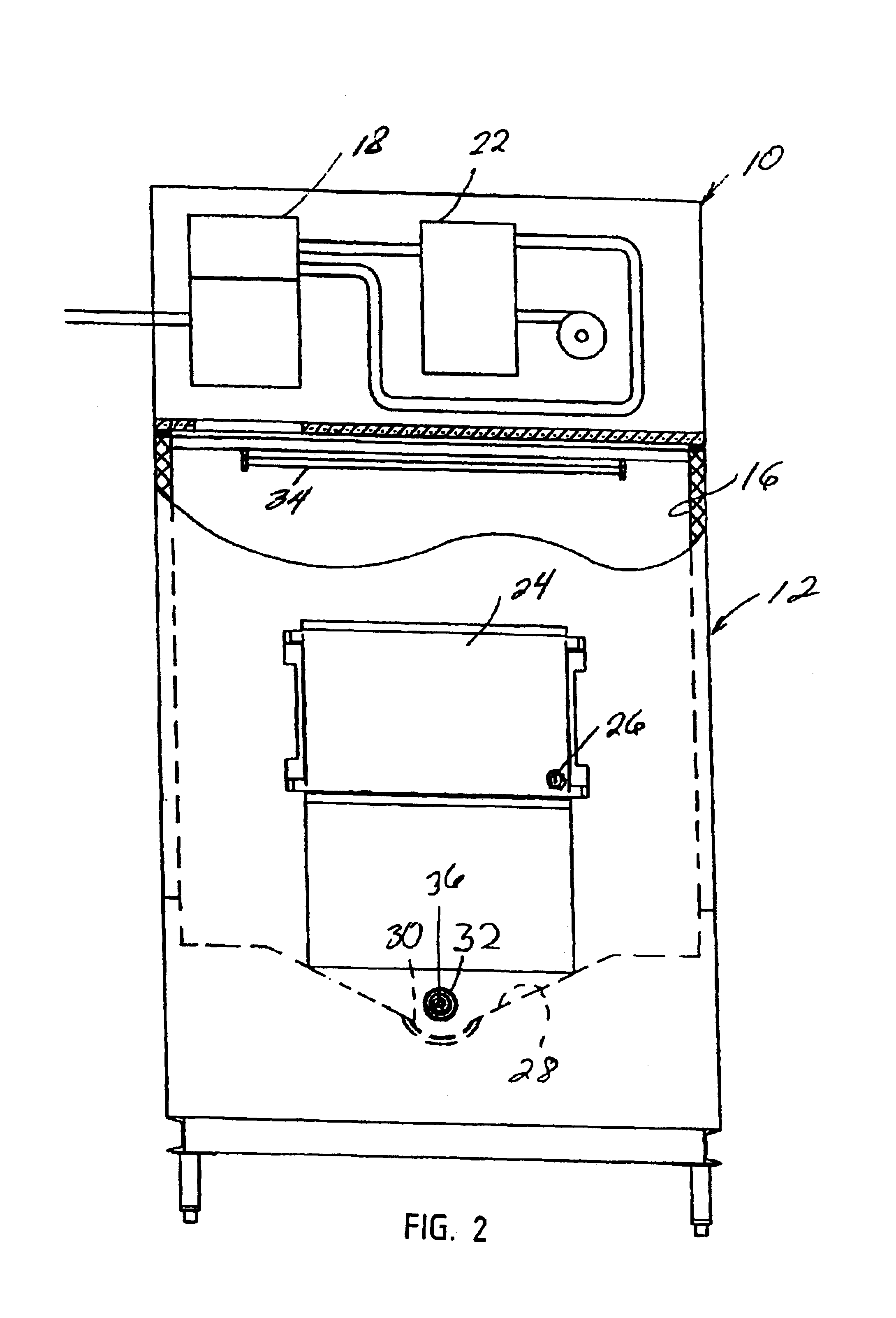
[0006]In a first separate aspect of the present invention, the ice delivery system includes a source of ice, an ice bin and two sets of at least one agitator each. Each set of at least one agitator includes a periodic cycle. The frequency of the periodic cycle of the set closest to the bin outlet is substantially greater than the frequency of the periodic cycle of the other set. Ice is thus able to move through the bin without bridging or blockage and, at the same time, without being excessively stirred.
[0028]In a twenty-third separate aspect of the present invention, the ice delivery system provides for the blowing of transporting air without release of the gate at the remote dispensing station. The blowing of transporting air with the gate closed at the remote station accommodates a drying cycle as well as a cleaning cycle without affecting the ice within the remote station.

Problems solved by technology

In operating such systems, ice has been found to have a tendency to stick together and form blockages in the handling system.
Localized thawing followed by re-freezing encourages the agglomeration of pieces of ice, resulting in blockage and inappropriate dispensing.
Contamination has been a problem in such systems.
Further, placing foreign objects, such as glasses and bowls, in the ice for chilling has also been found to be a common, if inappropriate, use of ice bins.

Method used


Image

  • Method and apparatus for the distribution of ice
  • Method and apparatus for the distribution of ice
  • Method and apparatus for the distribution of ice

Examples


second embodiment

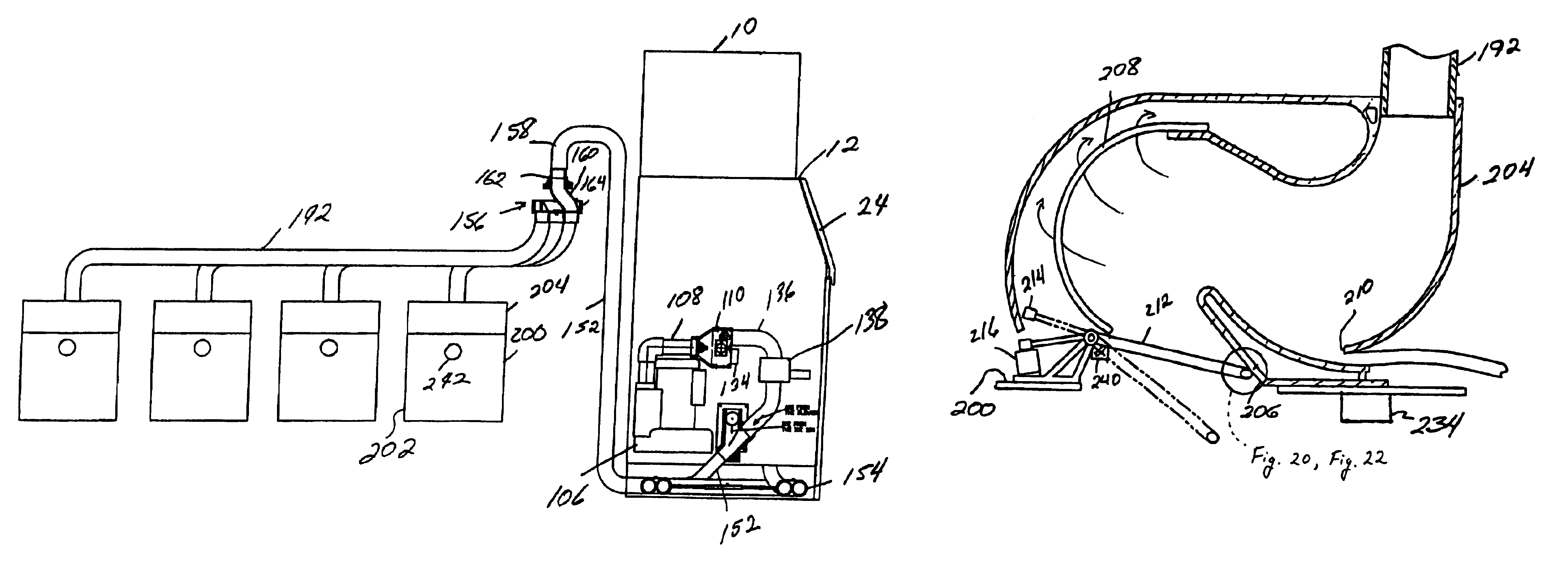
[0087]In the embodiment of FIGS. 21 and 22, the drain from the end of the gate is through a passage in the gate 212 itself. In this embodiment, bars 226 extend from the upper surface of the gate 212, overlaying a channel 228 offset to promote flow to one side of the gate 212 as can be seen in FIG. 21. A cup 230 receives the collected liquid and communicates with a discharge tube 232 to exhaust the liquid away from the ice storage bin 202 of the remote dispensing station 200. For either drain of these two embodiments to work, the gate 212 is to be closed for optimum operation. The second embodiment is better able to capture liquid even if there is a slight opening of the gate 212 within the passage 206.

[0088]The foregoing structure is preferably configured for operation with a controller. An electronic or microprocessor-based control system is preferred. The controller is contemplated to specifically control the mode of operation of each element and to provide responses to specific e...

first embodiment

[0108]an ice delivery system conduit coupling is illustrated in FIGS. 23 and 24. The coupling is preferably circular in cross section and is shown to be an integral tube, generally designated 244. The tube 244 is integral in the embodiment of FIG. 24 but is defined in two sections for purposes here as having a first end portion 246 and a second end portion 248. The first end portion 246 includes a tubular clamp section 250 while the second end portion 248 includes a tubular clamp section 252. Between the two clamp sections, the end portions 246 and 248 define tubular extension sections 254 and 256. These sections 254 and 256 include an inner truncated conical surface which is continuous in the embodiment of FIG. 24. These tubular extension sections 254 and 256 include outwardly facing inner shoulders 258 and 260. Between these shoulders, the inner surface of these sections defines a truncated conical surface with the diameter decreasing from the shoulder 258 toward the shoulder 260....


PUM


Abstract

An ice delivery system includes an ice bin with an ice maker thereon. An auger dispenses ice from the bin and agitators within the bin prevent blockage. The agitation may follow a pattern depending on the location of the agitators with some about the periphery less employed than those adjacent the auger. An ice gate receives ice and flowing air to direct the ice pneumatically to a multistation diverter. The flow through the diverter is vertically downwardly. Tubes from the diverter convey ice to remote dispensing stations. The dispensing stations have prechambers with drains and lockable gates to advantageously receive ice for delivery into the remote station bins or block the ice storage area to allow cleaning. Conduit couplings are configured to connect tubing without creating an area of ice blockage or allowing the buildup of contamination. Germicidal lights or ozone may be used in the ice bin to avoid contamination. Further, active agents for cleaning, de-scaling or sanitizing may be introduced through the ice gate on an automatic cycled basis.

Description

[0001]This is a divisional application of U.S. application Ser. No. 09 / 544,233, filed Apr. 7, 2000, issuing as U.S. Pat. No. 6,561,691, on May 13, 2003.BACKGROUND OF THE INVENTION[0002]The field of the present invention is pneumatic ice distribution to dispensing stations.[0003]Apparatus and methods for distributing ice to remote stations have been developed, particularly for use in the food service industry. Such systems incorporate a central ice bin, transport conduits, remote dispensing stations and a source of pneumatic energy to move the ice from the central bin to the dispensing stations. One such system is illustrated in U.S. Pat. No. 5,549,421, the disclosure of which is incorporated herein by reference.[0004]In designing such systems, important considerations include enhancing ice flow, maintaining the integrity of the ice in a frozen state and avoiding contamination. In operating such systems, ice has been found to have a tendency to stick together and form blockages in th...

Claims


Application Information

Patent Timeline
IPC IPC(8): F25C5/00
CPCF25C5/007F25C2400/12F25C5/24
Inventor MCCANN, GERALD P.VERLEY, DONALD J.ZATULOVSKY, LEONIDHUMPHREYS, RICHARD M.
Owner TMO ENTERPRISES
Learn More