Portable utility stand

a utility stand and portability technology, applied in the field of utility stands, can solve the problems of easy knocking, cumbersome transportation and setup, lack of stability, etc., and achieve the effect of less floor area, larger stabilizing floor footprint, and less floor spa

Inactive Publication Date: 2005-10-11
LARRICK GEORGE EDWARD +2
View PDF11 Cites 41 Cited by
  • Summary
  • Abstract
  • Description
  • Claims
  • Application Information

AI Technical Summary

Benefits of technology

[0014]The base with universal mounting receptacles allows right hand or left-hand users to set up the components, as they prefer. In addition, a user could use the same utility stand for multiple uses by using for example the artist's easel in place of the sheet music support platform.
[0027]Thus in accordance with the present invention, a stable portable utility stand that supports user requirements for comfortable seating, displaying sheet music or other work in progress, storing accessories and reference material, supporting auxiliary equipment such as a microphone and providing a reference table is easily collapsed and setup.

Problems solved by technology

First, as individual pieces of equipment they lack stability and are easily knocked over because of their small support bases.
Because they are separate pieces they are cumbersome to transport and setup.
Also, the separate pieces of equipment require a larger total floor area than a single integrated utility stand.
Moreover, these separate pieces of equipment duplicate functions of the individual pieces and therefore more parts are fabricated than necessary.
Another problem with portable work stations and music stands is the lack of convenient storage for tools, reference material, sheet music, and accessories, e.g. tools, paint brushes, pencils, guitar strings, markers, tuning devices to name a few which a user may require for work, study, or practice.
Another problem is the lack of comfortable seating that can be adjusted to the user needs and workstation level.

Method used


Image

  • Portable utility stand
  • Portable utility stand
  • Portable utility stand

Examples


Embodiment Construction

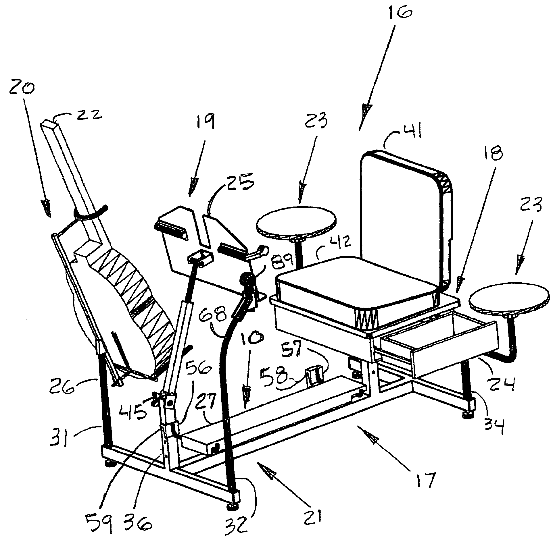
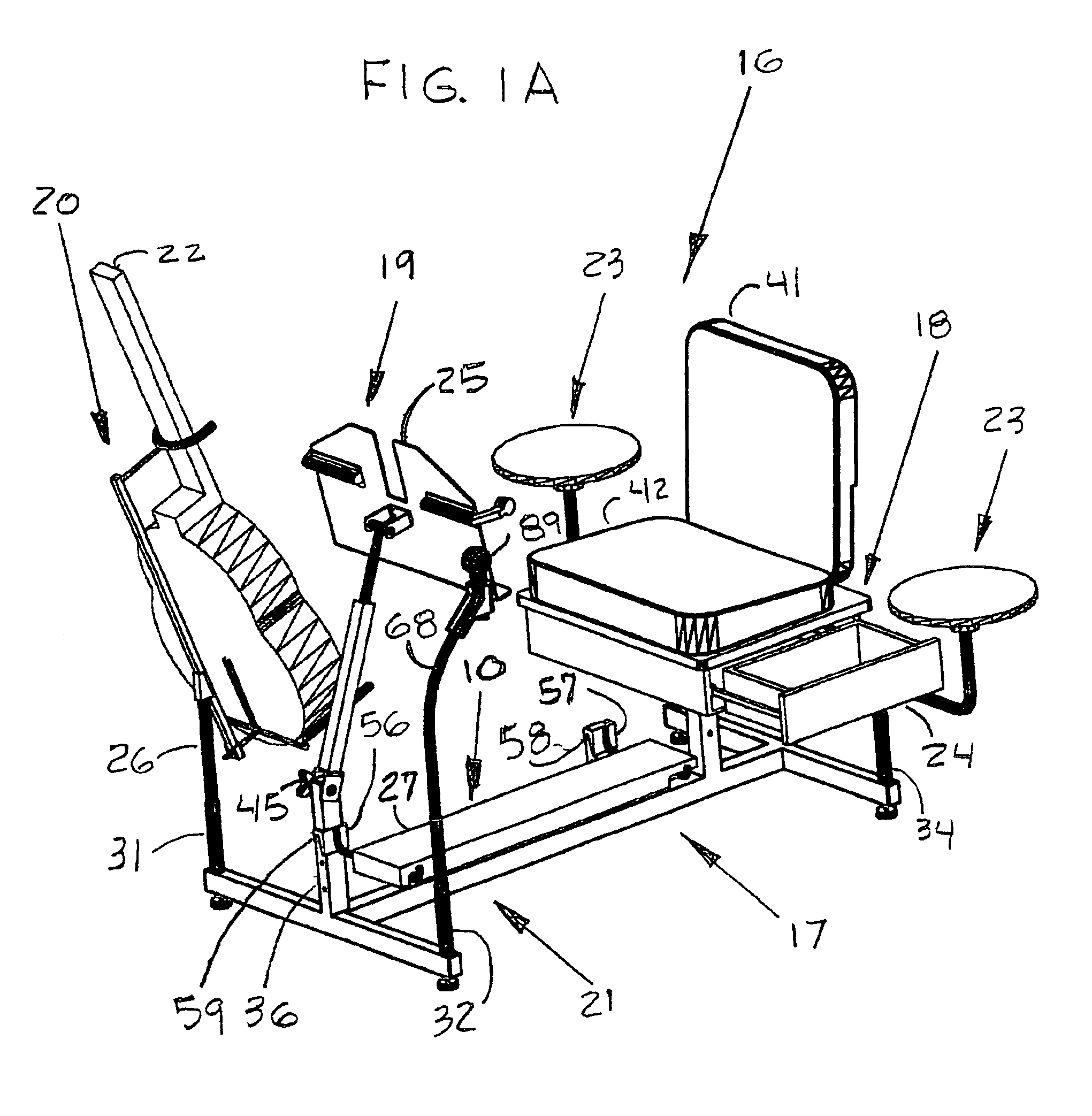
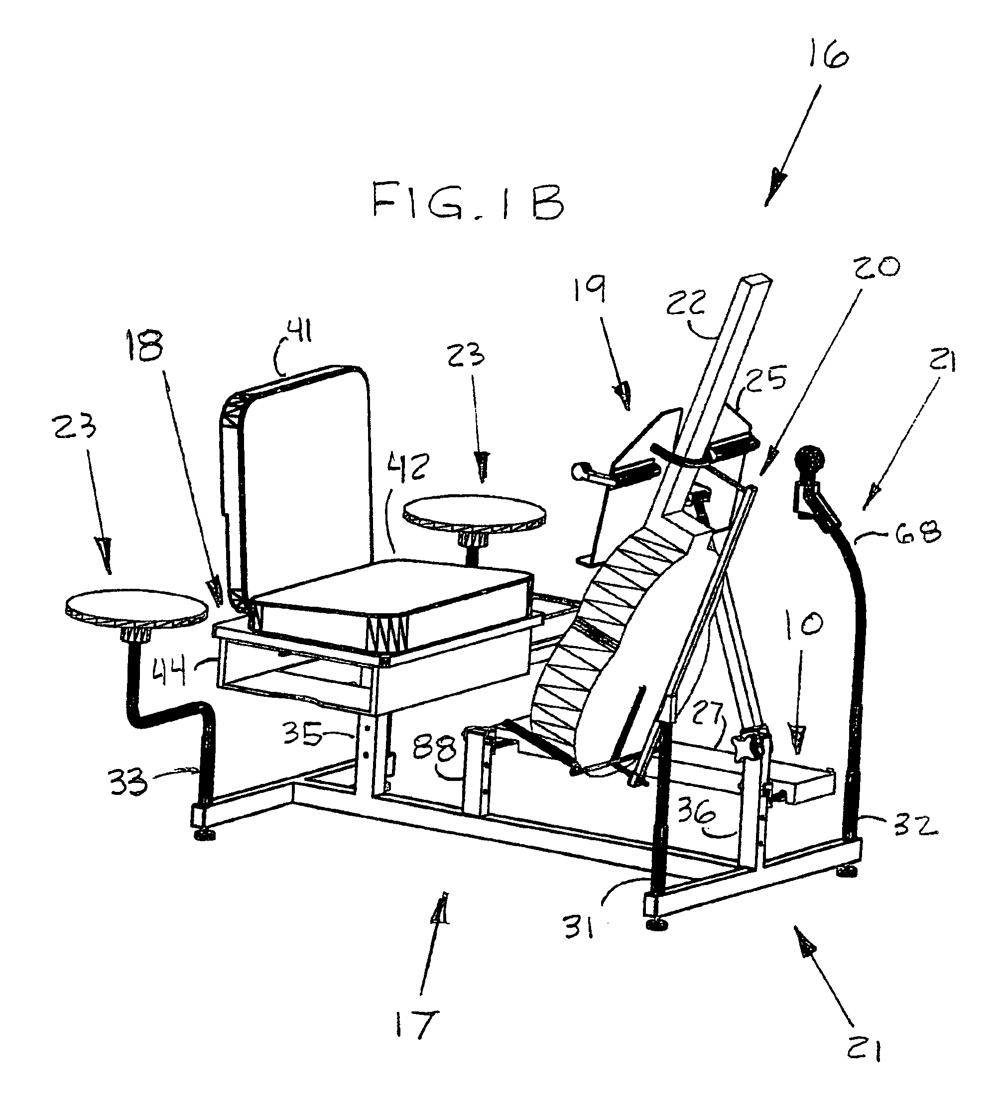
[0057]The utility stand top assembly 16 is shown in FIG. 1A and FIG. 1B. The eight subassemblies that comprise the utility stand 16 include:[0058]1. A base frame subassembly 17, see FIG. 4[0059]2. A seating bench / storage subassembly 18, see FIG. 5A, FIG. 5B, and FIG. 5C[0060]3. A sheet music support subassembly 19, see FIG. 8[0061]4. A rotatable instrument support subassembly 20, see FIGS. 7A and 7B[0062]5. An auxiliary equipment support subassembly 21, see FIG. 10[0063]6. A foot rest subassembly 10, see FIGS. 6A and 6B[0064]7. An auxiliary shelf subassembly 23, see FIG. 9[0065]8. An extension arm subassembly 43, see FIGS. 2, 7A and 7B

[0066]FIGS. 1A and 1B show the utility stand top assembly 16. The adjustable seating bench / storage subassembly 18 is shown with the drawer 24 open. The sheet music support subassembly 19 is shown with the platform 25 facing the seating bench / storage unit 18 where the user would be seated. The rotatable instrument support subassembly 20 is shown support...


PUM


Abstract

A portable utility stand that integrates the equipment required by users such as musicians, artists, and surveyors. These users generally require a lighted work platform, a tool or instrument support, a comfortable adjustable seat, a storage area for equipment such as tools, an adjustable footrest, shelf to temporarily place equipment, a means to support equipment such as, microphones, tuning devices or a telephone. The equipment is mounted to a base platform equipped with mounting receptacles that allow the user to arrange, adjust, and select suitable equipment for a particular application and in a preferred arrangement. The base platform is essentially a single member with receptacles for equipment mounting. A seating bench with storage unit is centrally located with respect to the mounting receptacles. Floor glides are mounted on bottom extreme ends. Disassembly simply requires removing the receptacle mounted equipment.

Description

BACKGROUND OF THE INVENTION[0001]The present invention relates to a utility stand. More particularly to a utility stand for users requiring a portable work / utility stand. The utility stand incorporates the basic equipment a musician, surveyor, artist, or any user that requires a complete platform for work, practice or performing into a single structure that is easily disassembled or collapsed for storage and transport between uses.[0002]Prior art includes examples of a Portable Workstation, U.S. Pat. No. 6,068,355, a Portable Music Stand, U.S. Pat. No. 6,264,161. Other Portable equipment used by musicians, surveyors, and artists among others include portable footrests, portable instrument support stands, and portable reference tables and portable microphone stands.[0003]While having some utility these separate components have several major drawbacks. First, as individual pieces of equipment they lack stability and are easily knocked over because of their small support bases. Because...

Claims


Application Information

Patent Timeline
Patent Type & Authority Patents(United States)
IPC IPC(8): A47C9/08A47C9/00
CPCA47C9/08
Inventor LARRICK, GEORGE EDWARDLARRICK, MARY TERESALARRICK, DANIEL EDWARD
Owner LARRICK GEORGE EDWARD
Why Eureka
Try Eureka