Rigid corrugated bulk container for liquids and semi-liquid fluids

a corrugated bulk container and liquid/liquid fluid technology, applied in the field of corrugated bulk container, can solve problems such as the need for fillers, and achieve the effect of easy collaps

Active Publication Date: 2005-02-24
INT PAPER CO
View PDF32 Cites 43 Cited by
  • Summary
  • Abstract
  • Description
  • Claims
  • Application Information

AI Technical Summary

Benefits of technology

[0005] The present invention is an economical corrugated bulk container that can be purchased as a fully assembled, ready to fill unit for shipping, storing and dispensing liquids or semi-liquid fluids, that can be filled using an automated tote or drum filling station, and that can be easily collapsed and disposed of by an end user after use.

Problems solved by technology

Another disadvantage of these prior art systems is the need for the filler to reach into the bottom of the package, which can be 35 inches or more deep, in order to attach the fill valve mechanism through which the bag is filled.

Method used


Image

  • Rigid corrugated bulk container for liquids and semi-liquid fluids
  • Rigid corrugated bulk container for liquids and semi-liquid fluids
  • Rigid corrugated bulk container for liquids and semi-liquid fluids

Examples


first embodiment

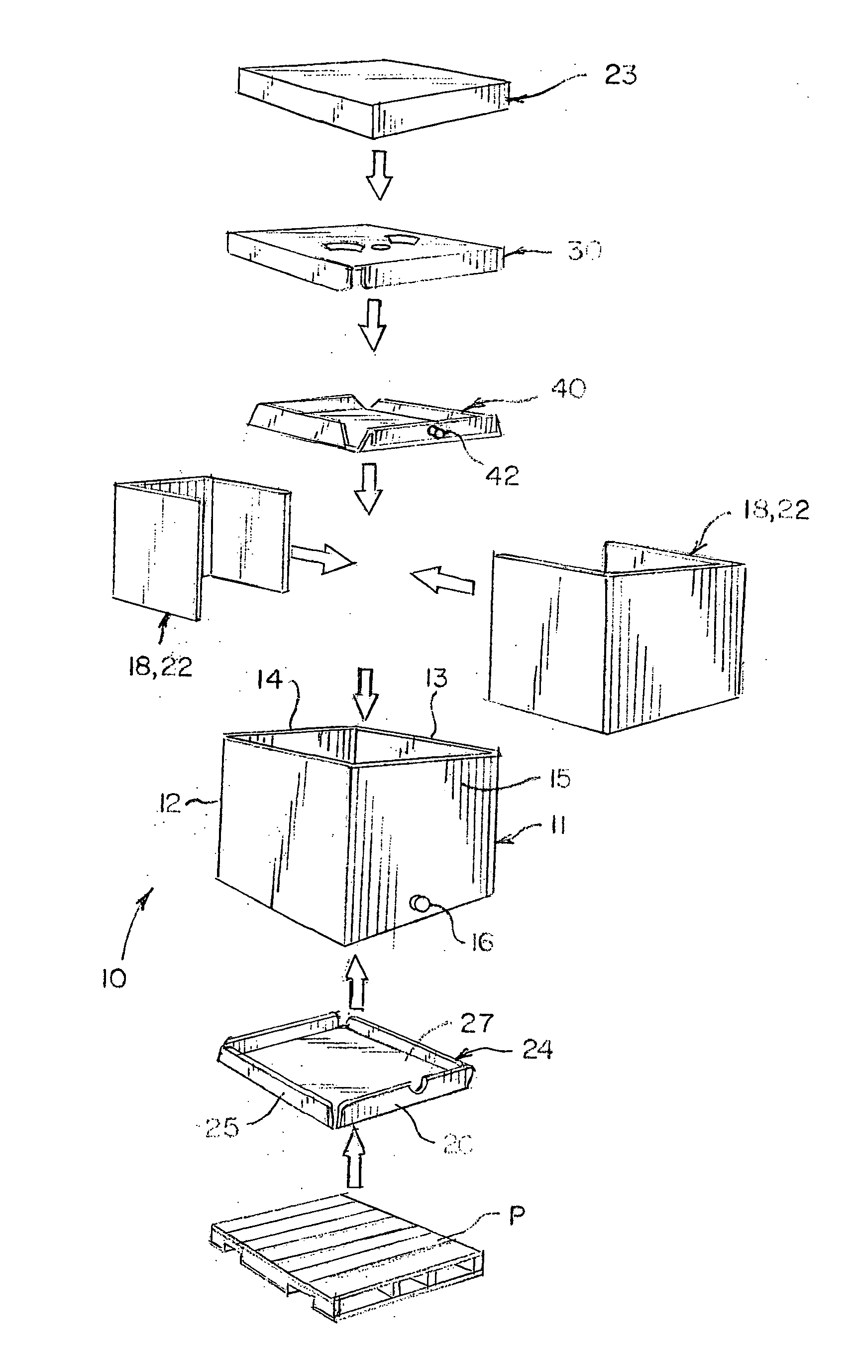
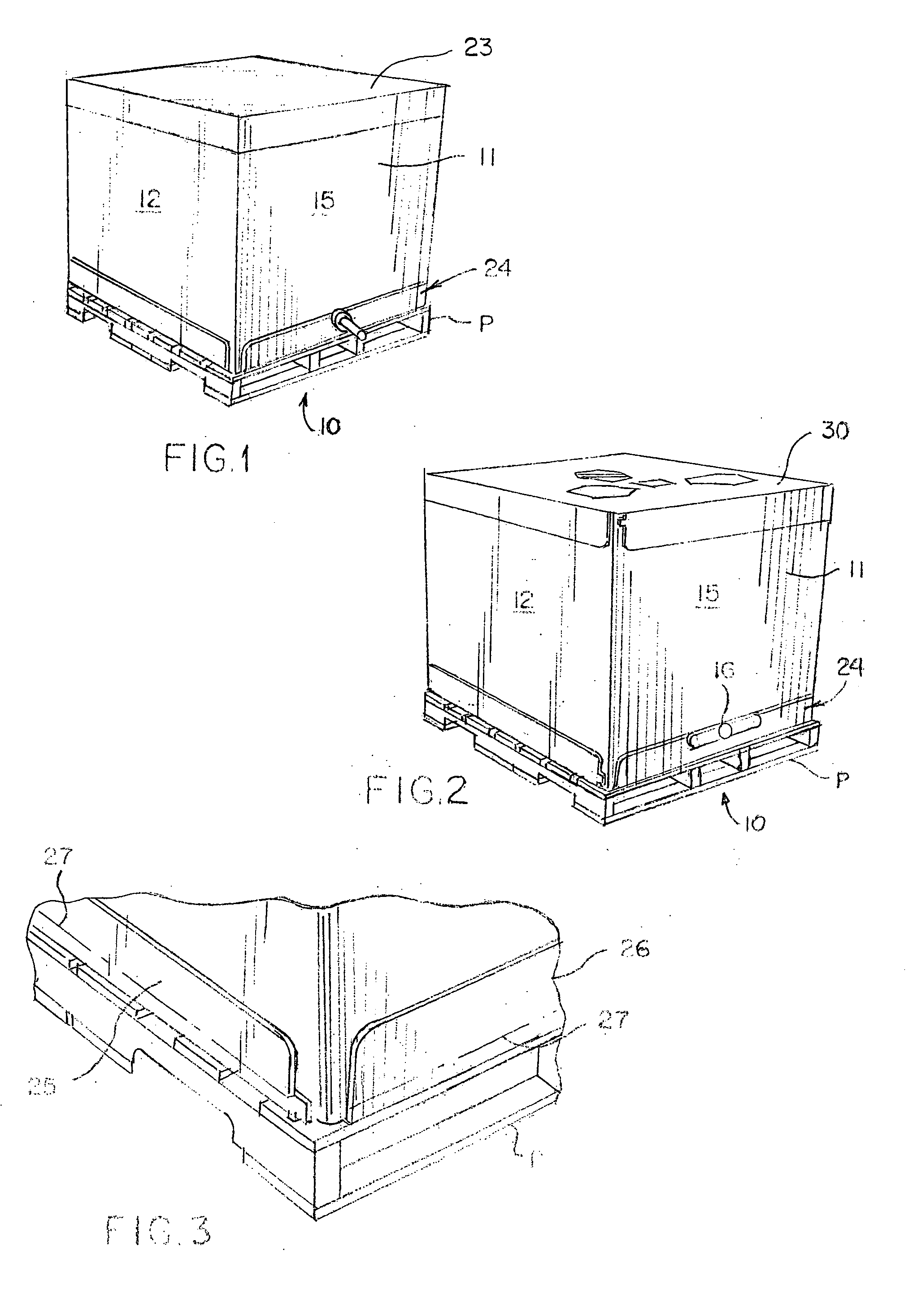
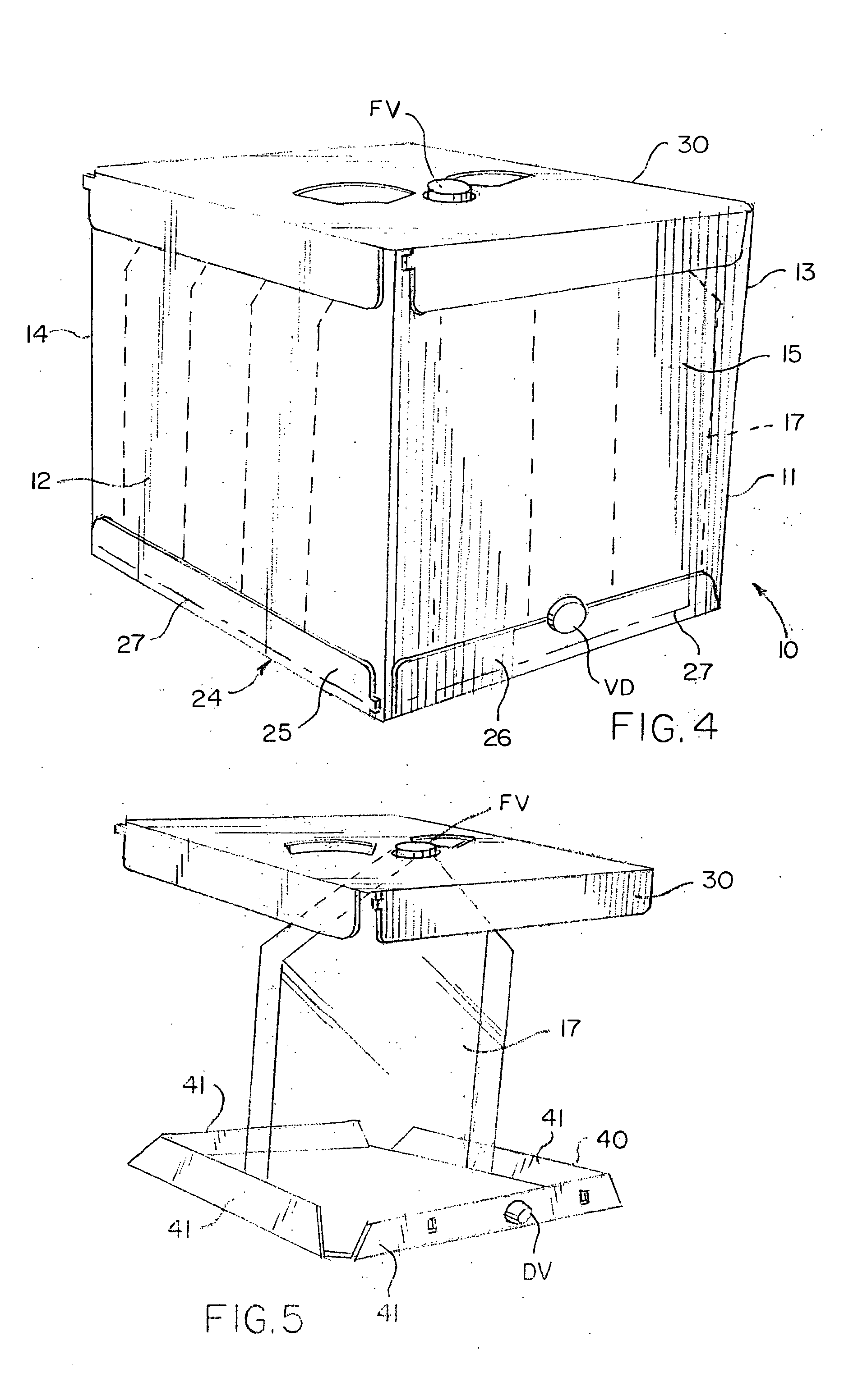
[0057] corrugated container according to the invention is indicated generally at 10 in FIGS. 1, 2 and 15. The container comprises an open-ended side wall tube 11 of triple wall laminated construction, having two length panels 12 and 13 and two width panels 14 and 15, that can be of varying length and widths. A dispensing valve hole 16 is cut into one width panel of the tube for receiving a dispensing valve attached to a bag 17 supported in the container. The triple wall tube provides vertical compression resistance for stacking strength, and improved bulge resistance to an internally positioned bag. Further bulge resistance may be achieved by adding one or more inserts 18 along the inside of the length and width panels. See FIGS. 7-9 and 15. The inserts may comprise single panels 20 (FIG. 7) fitted against the inside surface of one or more of the side walls, and preferably at least on the length panels, or L-shaped inserts 21 (FIG. 8) that fit against a length panel and wrap around ...

embodiment 10

[0067] The preferred embodiment 50 differs from the previous embodiment 10 primarily in the construction of the fill valve support plate 51. As seen best in FIGS. 17, 18, 21 and 22, the fill valve support plate 51 comprises a rectangular panel 52 having a flap 53 foldably connected to each side edge, as before, but the structure for holding and supporting the fill valve is substantially different and provides a much stronger arrangement. A first series of cuts 54 are made in the panel to define three sides of a rectangularly shaped area 55 that is located so that it will be centered on the fill valve when the fill valve support plate is in its operative position on the container. The cuts 54 do not completely separate the material bordered by the cuts from the surrounding panel, but define frangible score lines that can be torn to remove the panel 56 bordered by the cuts. The fourth side 57 of this area is defined by a cut that completely separates that edge of the panel 56 from the...


PUM


Abstract

A corrugated bulk container for shipping, storing and dispensing liquids and semi-liquid fluids. The container is a laminated triple wall open-ended tube having side walls and end walls, and a bag assembly is supported in the tube for containing the liquid or semi-liquid fluid. The bag assembly includes a bag having a fill valve and a dispensing valve attached to it, a bag cassette to which a bottom end of the bag is attached, and a fill valve support plate to which a top end of the bag is attached. The bag cassette has structure to receive and hold the dispensing valve in position relative to a dispensing valve opening in the tube, and the fill valve support plate has structure to receive and support the fill valve. The container is attached to a pallet by severable structure, and the fill valve support plate is attached to the tube by severable structure so that the bag assembly can be removed from the container, for easy collapse of the container for disposal or recycling. Fill valve support structure is cut from the fill valve support plate and folded into a position to receive and support the fill valve.

Description

[0001] This application claims the benefit of U.S. provisional patent application Ser. No. 60 / 492,524, filed Aug. 5, 2004.FIELD OF THE INVENTION [0002] This invention relates generally to packaging for shipping and storing bulk quantities of product. In particular, the invention relates to a packaging system for shipping, storing and dispensing liquid or semi-liquid fluids, and more specifically to a corrugated container and supported bag that are fully assembled and ready to use, thereby enabling a user to fill the bag without first having to assemble part or all of the container, and wherein the container can be easily collapsed and disposed of when it is empty. BACKGROUND ART [0003] Conventional containers for use in shipping, storing and dispensing liquid or semi-liquid fluids often consist of either “bottle and cage” arrangements, or composite corrugated containers. The “bottle and cage” arrangements comprise a semi-rigid plastic bottle that is supported within a wire-bound ext...

Claims


Application Information

Patent Timeline
Patent Type & Authority Applications(United States)
IPC IPC(8): B65D77/06
CPCB65D77/067B65D77/061
Inventor CHURVIS, MICHAELGATES, LAWRENCE A.MOSS, WILLIAM F.RIGGINS, PAMELA JEAN
Owner INT PAPER CO
Why Eureka
Try Eureka