Reflector apparatus for a tubular light source

Inactive Publication Date: 2005-10-11
NORTH AMERICAN LIGHTING
View PDF21 Cites 78 Cited by
  • Summary
  • Abstract
  • Description
  • Claims
  • Application Information

AI Technical Summary

Problems solved by technology

One disadvantage of tubular lighting devices, such as device 5, is that, because of the location of the light source, the amount of controlled light (i.e., light directed to the aperture) may not be optimized because of the location of the light source.
Consequently, the overall illumination efficiency of the lighting device may be adversely affected.
One reason that efficiency may be adversely affected is that a reflector has a relatively large height in comparison to the depth of the reflector.
For tubular reflectors having relatively small apertures, light emanating from a light source, reflected by the reflector, and hence directed towards the reflector aperture is limited.
Consequently, a portion of the overall illuminated light does not enhance the overall efficiency of the reflector, and therefore the ef

Method used


Image

  • Reflector apparatus for a tubular light source
  • Reflector apparatus for a tubular light source
  • Reflector apparatus for a tubular light source

Examples


Embodiment Construction

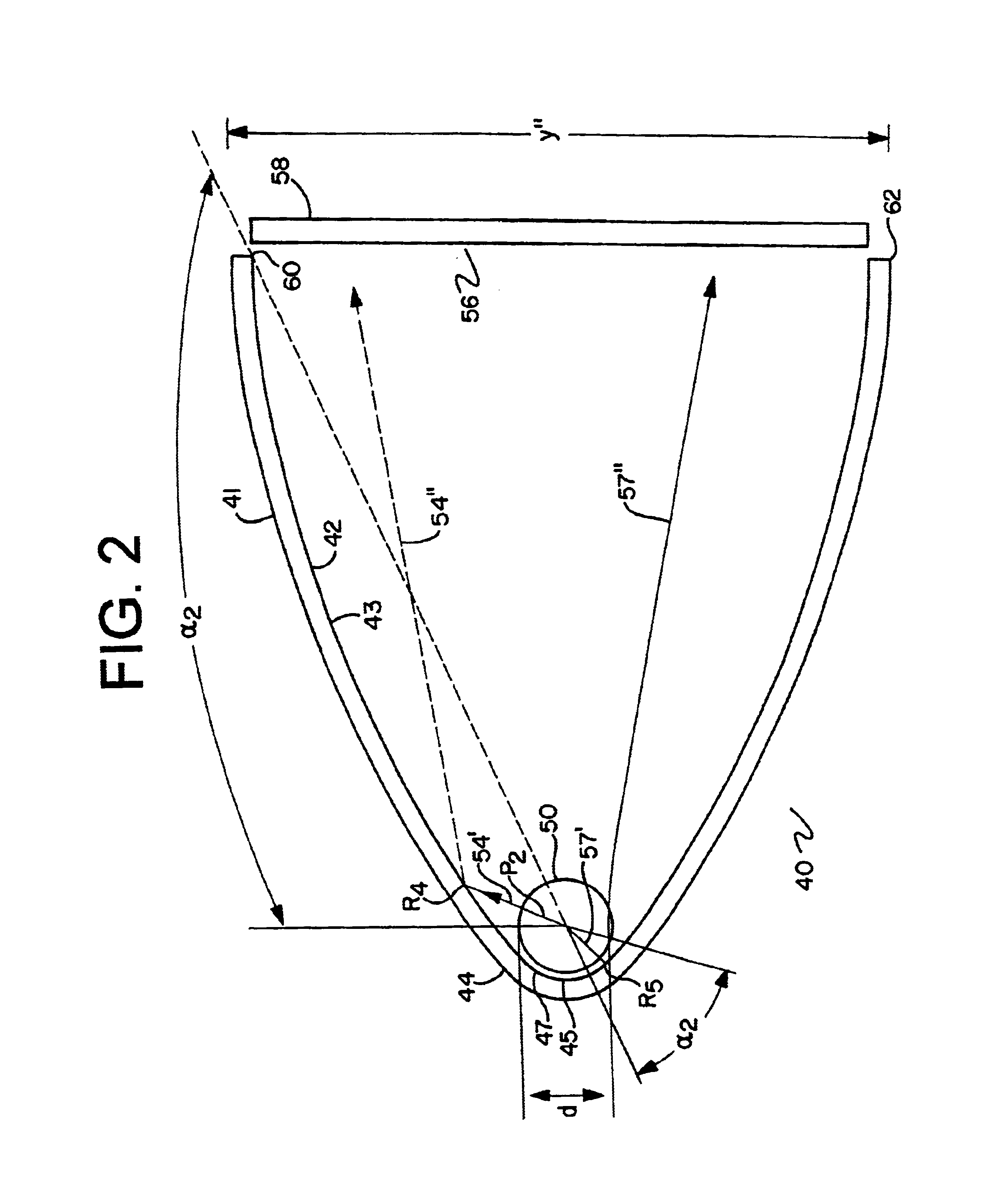
[0023]FIG. 2 illustrates a cross sectional view of a tubular lighting reflector 40 incorporating a preferred embodiment of the present invention. Lighting device 40 includes a reflector 41 having a generally smooth internally reflective surface 42 extending from a first surface end 60 of the reflector 41 to a second surface end 62 of the reflector 41. The distance between the surface ends 60, 62 defines a reflector aperture 56. In the exemplary embodiment illustrated in FIG. 2, the height of the aperture is represented by y.” Preferably, surface 42 includes a reflective finish 43 such as aluminum metalization. Other reflective finishes such as argent paint or chrome coating may also be used.

[0024]Reflector 40 also includes a reflector portion 44 having a reflective surface 45. A tubular light producing element 50 is positioned within the reflector portion 44. Preferably, reflector portion 44 is a semi-circular reflector and reflective surface 45 includes a reflective finish 47 simil...


PUM


Abstract

A tubular reflector for reflecting light emanating from a tubular light source. The tubular reflector may be semi-circular or elliptical in shape and positioned around the tubular light source. Furthermore, the inner reflective surface of the tubular reflector may be smooth or multi-faceted. The reflector may reflect light from the tubular light source and redirect the light to achieve a desired distribution pattern.

Description

BACKGROUND[0001]1. Field of Invention[0002]The present invention relates to the field of tubular reflecting. More particularly, the present invention relates to a tubular reflector and a tubular lighting device for automotive lighting.[0003]2. Background of the Invention[0004]There is generally an increasing need, particularly in the automotive lighting industry, for tubular light source applications. For example, one such application may be to a Center High Mount Stop Lamp (i.e., CHMSL). Tubular light sources used in such applications may be mounted within an elongated reflector having a parabolically shaped reflecting surface. For example, FIG. 1 illustrates a tubular lighting device 5 having a height y and having a tubular light source 10 situated within a parabolic reflector 20. The reflector 20 has a first aperture end 26 and a second aperture end 28, the distance between the two ends 26, 28 (i.e., distance y) defines a reflector aperture 35.[0005]Reflector 20 includes a parabo...

Claims


Application Information

Patent Timeline
IPC IPC(8): F21V7/04F21V7/00
CPCF21S48/1376F21Y2103/00F21S41/337
Inventor JIAO, JIANZHONGLEKSON, MATTHEW A.
Owner NORTH AMERICAN LIGHTING
Why Eureka
Try Eureka