Radar apparatus for detecting a direction of a center of a target

a radar apparatus and center scanning technology, applied in the direction of reradiation, measurement devices, instruments, etc., can solve the problems of inability of the above-mentioned radar apparatus to determine the center scanning angle of the radar unit, the radiation radar beam is not uniform, and the radar apparatus cannot accurately detect the center scanning angle. to achieve the effect of accurate detection of the center

Inactive Publication Date: 2002-06-04
TOYOTA JIDOSHA KK
View PDF19 Cites 62 Cited by
  • Summary
  • Abstract
  • Description
  • Claims
  • Application Information

AI Technical Summary

Benefits of technology

The radar apparatus of the present invention can determine a direction of a center of the target by performing the similarity approximation even when the reflection of the radiation beam on the target is not uniform and noises are superimposed in the received reflection beams. Accordingly, it is possible for the radar apparatus of the present invention to accurately detect the direction of the center of the target for a center scanning angle of the radar unit.

Problems solved by technology

However, in a case of the radar apparatus of this type, the radar apparatus receive reflection radar beams containing noises from the reflectors of the advancing vehicle, and the reflection of the radiation radar beam on the advancing vehicle is not uniform.
It is difficult for the above-mentioned radar apparatus to accurately detect a position of an end of the advancing vehicle by measuring the time for the radiation radar beam to return to the radar apparatus after it has been reflected off the advancing vehicle.
It is practically impossible for the above-mentioned radar apparatus to determine a center scanning angle of the radar unit for a center of the advancing vehicle by detecting a mid-point between two scanning angles for the reflectors as in the laser-beam radar apparatus.
Therefore, when the conventional radar apparatus utilizing the radar unit radiating the EHF electromagnetic wave is used, it is difficult to accurately detect the direction of the center of the target.

Method used


Image

  • Radar apparatus for detecting a direction of a center of a target
  • Radar apparatus for detecting a direction of a center of a target
  • Radar apparatus for detecting a direction of a center of a target

Examples


Embodiment Construction

A description will now be given of the preferred embodiments of the present invention with reference to the accompanying drawings.

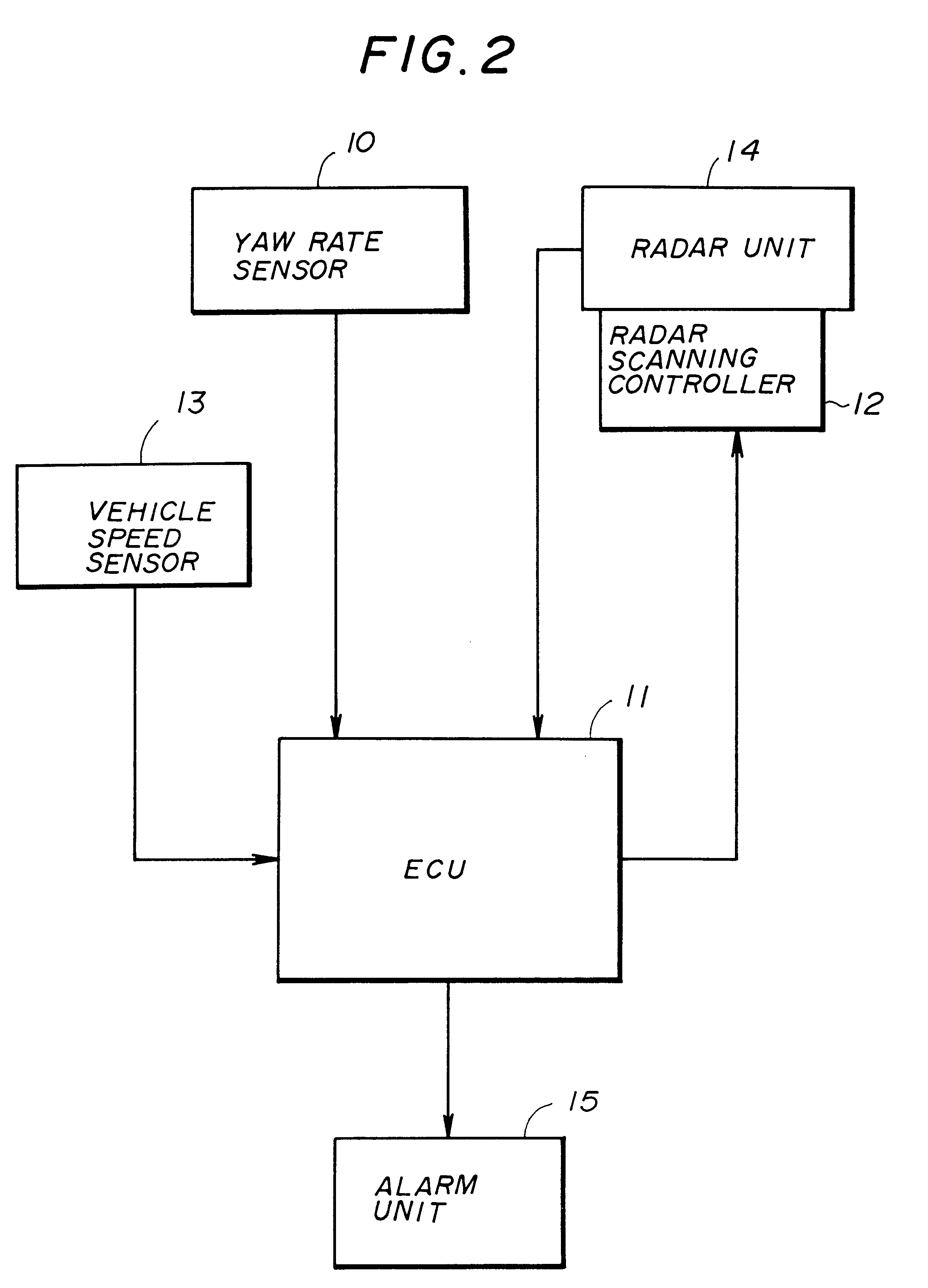
FIG. 2 shows a radar apparatus in one embodiment of the present invention. This radar apparatus is installed on an automotive vehicle.

Referring to FIG. 2, the radar apparatus of the present embodiment comprises a yaw rate sensor 10, an electronic control unit (ECU) 11, a radar scanning controller 12, a vehicle speed sensor 13 and a radar unit 14. The radar apparatus of the present embodiment further includes an alarm unit 15.

The yaw rate sensor 10 generates a yaw rate signal indicative of a measured yaw rate of the vehicle by using an acceleration sensor having a piezoelectric element, and supplies the yaw rate signal to the ECU 11.

The vehicle speed sensor 13 generates a vehicle speed signal indicative of a measured vehicle speed of the vehicle, and supplies the vehicle speed signal to the ECU 11.

The ECU 11 receives the vehicle speed signal from the vehic...


PUM


Abstract

A radar apparatus of an automotive vehicle includes a radar unit which radiates an electromagnetic wave to a target in a forward direction of the vehicle and receives reflection beams from the target to detect the target. A scanning control unit performs a beam scanning of the radar unit to the target so that the reflection beams during the beam scanning are received. A center direction determining unit detects a distribution pattern of the received reflection beams with respect to respective scanning angles of the radar unit, performs a similarity approximation of the distribution pattern by using an antenna directional gain pattern of the radar unit to produce an approximated distribution pattern, and determines a direction of a center of the target based on a peak of the approximated distribution pattern.

Description

BACKGROUND OF THE INVENTION(1) Field of the InventionThe present invention generally relates to a scanning radar apparatus, and more particularly to a scanning radar apparatus of an automotive vehicle which detects a direction of a center of a target, such as an advancing vehicle, by receiving reflection beams from the target.(2) Description of the Related ArtIn recent years, several types of radar devices for use in automotive vehicle have been developed in order to provide increased stability and operability of the automotive vehicle. The radar devices are capable of detecting a relative distance between a target (such as an advancing vehicle) and the vehicle, and a relative velocity of the target to a vehicle speed of the vehicle.Japanese Laid-Open Patent Application No. 4-158293 teaches a radar apparatus which is one of the above-mentioned types. The radar apparatus utilizes a radar unit radiating a laser beam in order to detect a target such as an advancing vehicle in a forward...

Claims


Application Information

Patent Timeline
Patent Type & Authority Patents(United States)
IPC IPC(8): G01S13/93G01S13/00G01S13/34G01S13/42G01S7/03G01S7/02G01S7/41G01S7/288G01S7/285G01S13/931
CPCG01S7/032G01S7/411G01S13/345G01S13/42G01S13/424G01S13/931G01S2013/9319G01S2013/93185G01S2013/932G01S7/2883
Inventor YAMADA, YUKINORI
Owner TOYOTA JIDOSHA KK
Why Eureka
Try Eureka