Vehicular marker lamp

a marker lamp and headlamp technology, applied in the manufacture of electric discharge tubes/lamps, electrode systems, lighting and heating apparatuses, etc., can solve the problem of forward visibility decline, and achieve the effect of reducing the number of light source units stored in the lamp chamber

Inactive Publication Date: 2009-04-16
KOITO MFG CO LTD
View PDF9 Cites 61 Cited by
  • Summary
  • Abstract
  • Description
  • Claims
  • Application Information

AI Technical Summary

Benefits of technology

[0012]The inventor has conceived that employing a configuration such as that disclosed in Patent Document 2 described above (i.e., a structure by which the low-beam distribution pattern and the high-beam distribution pattern can both be formed) as respective projection light source units stored in a lamp chamber in a lamp configuration such as that disclosed in Patent Document 1 described above allows the number of light source units stored in the lamp chamber to be reduced and the lamp chamber to be made small (allows a headlamp to be made compact).

Problems solved by technology

However, there was a problem that a band-shaped dark zone Dz appears along a horizontal line H-H in the high-beam distribution pattern (see FIG. 16), whereby the forward visibility decreases.

Method used


Image

  • Vehicular marker lamp
  • Vehicular marker lamp
  • Vehicular marker lamp

Examples


second embodiment

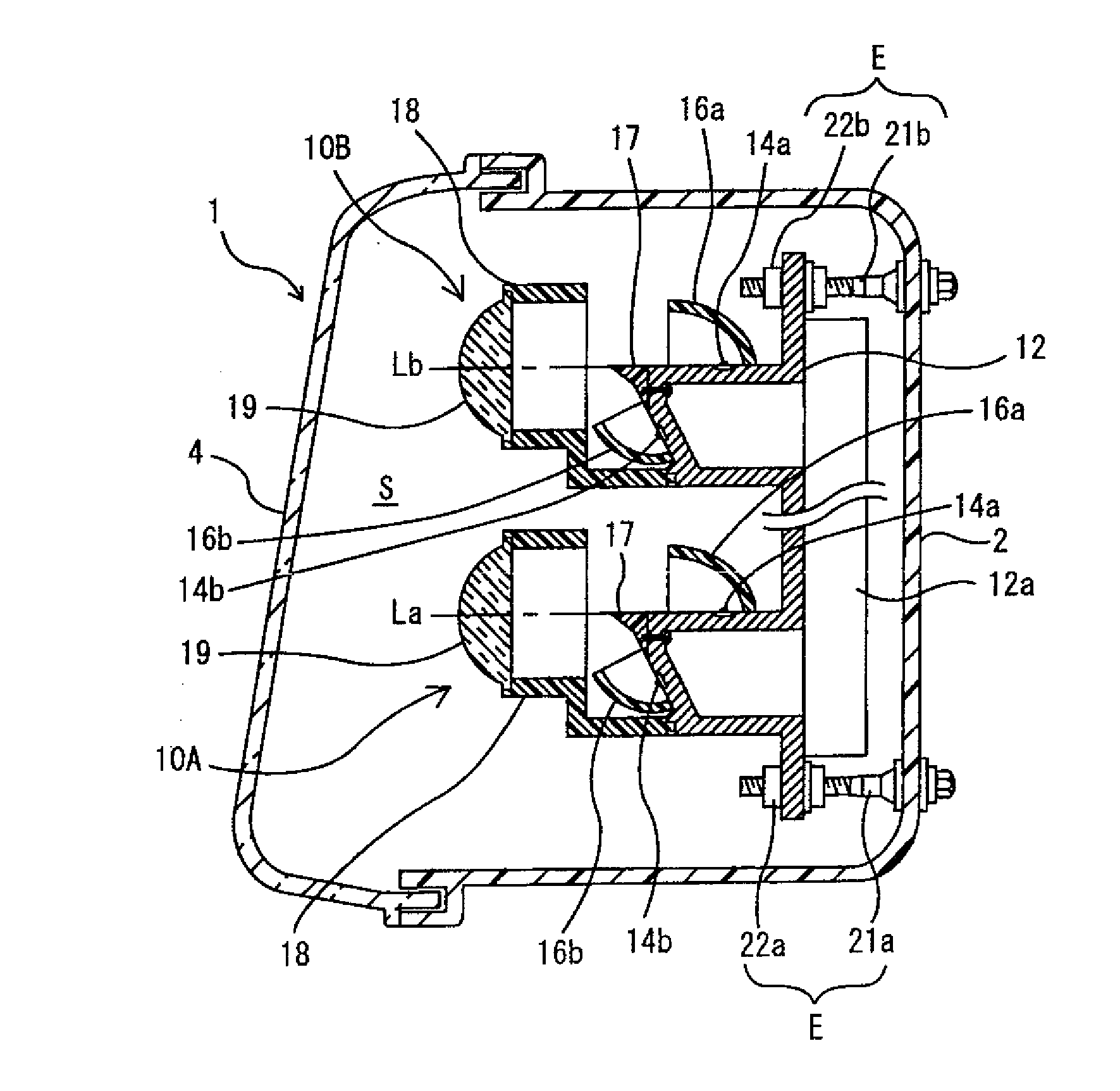
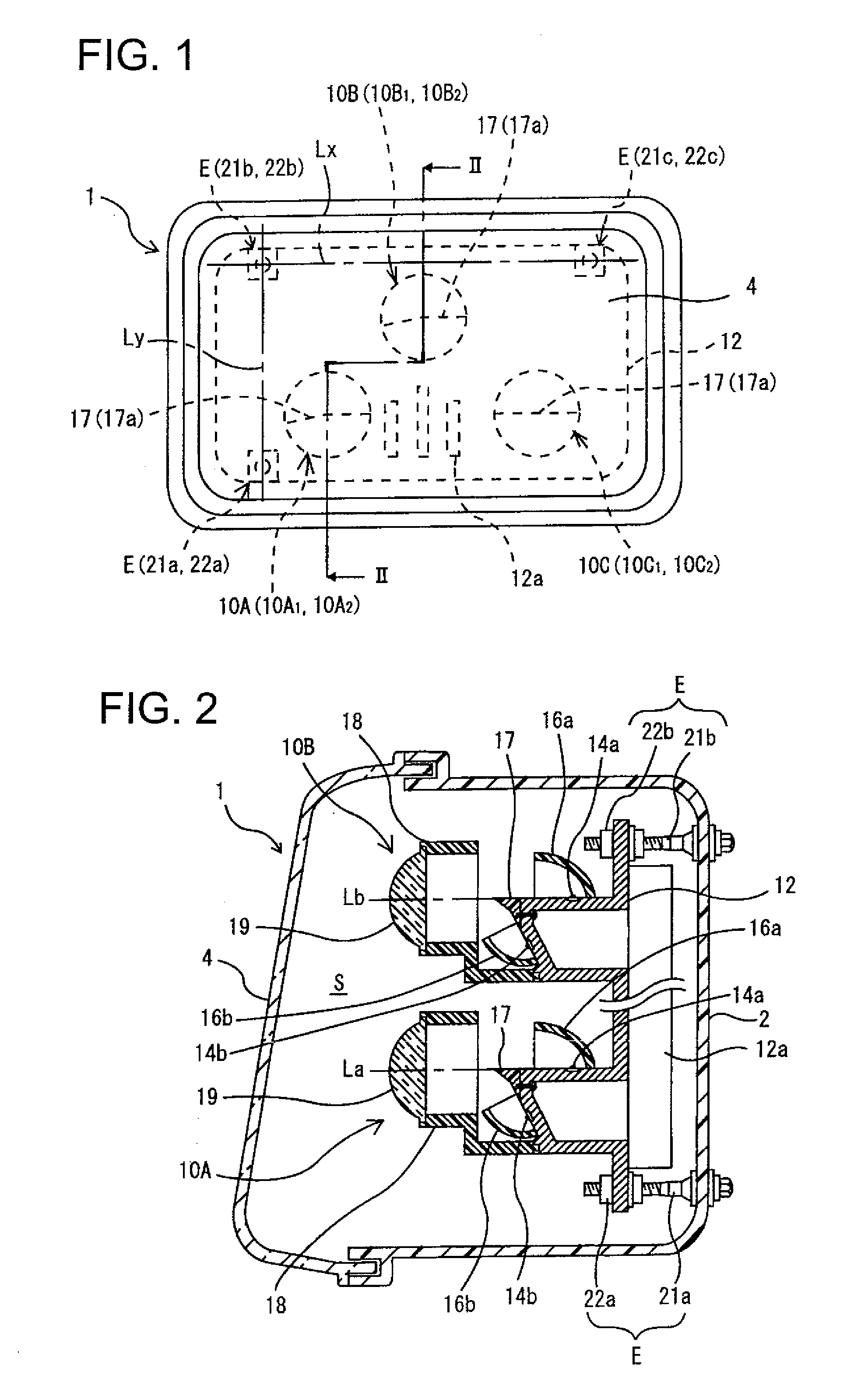
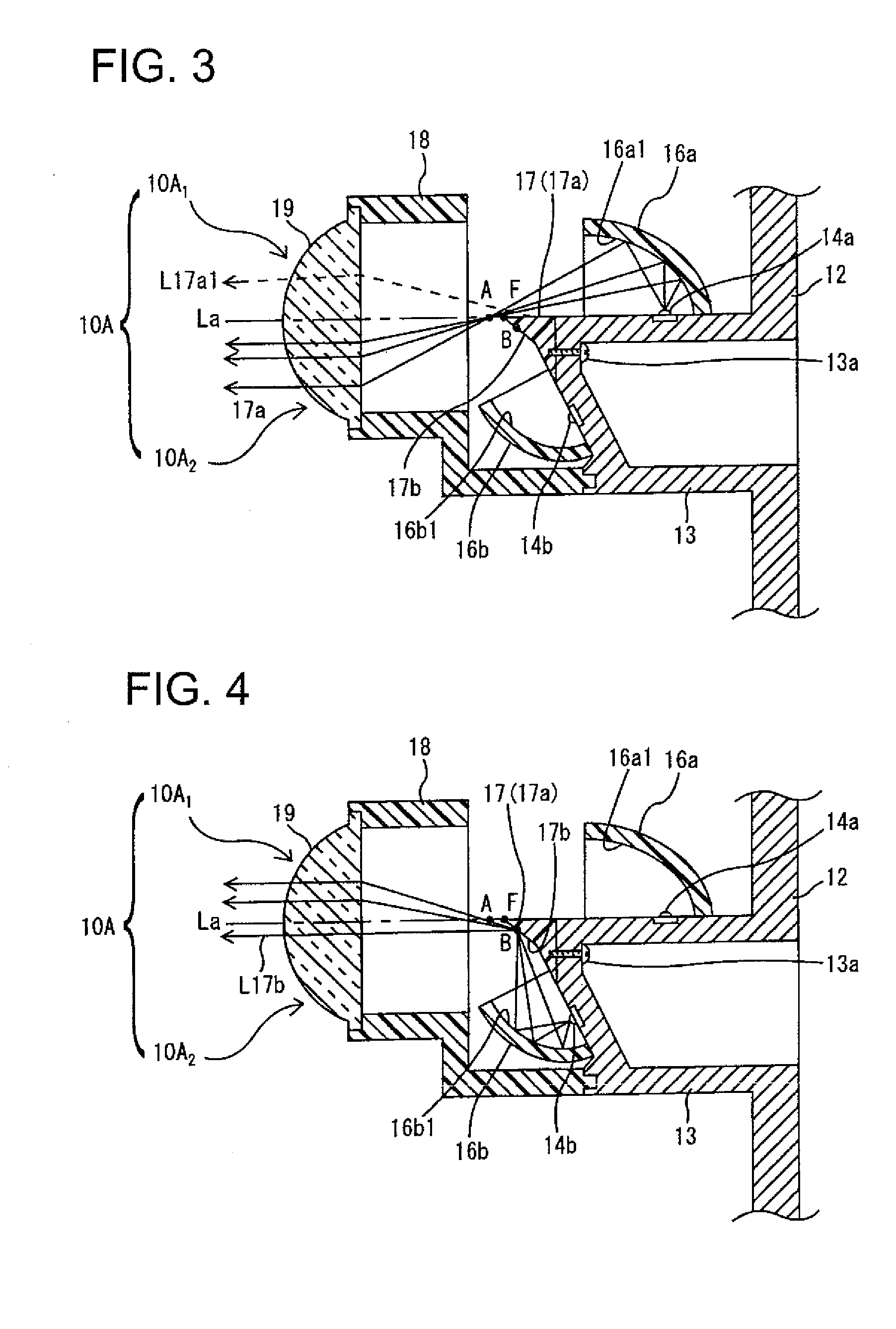
[0088]FIG. 9 is a vertical sectional view of a projection light source unit forming a projection light source unit assembly as a main section of an automobile headlamp of the present invention.

[0089]In the first embodiment described above, the light-emitting element 14b on the lower side and the reflector 16b on the lower side forming the respective projection light source units 10A, 10B, and 10C are provided to the front-side inclined surface of the swelling section 13, which is steeper than the downward reflective surface 17b, whereby reflected light from the reflector 16b converges in the point B. However, in this embodiment, reflected light from a reflector 16c converges in the point A.

[0090]That is, on the front surface side of the bracket 12, a pair of upper and lower flat plate-shaped protrusion sections 13a and 13b are provided instead of the forward swelling section 13 in the first embodiment described above, the lens holder 18 is attached to a front end section of the lowe...


PUM


Abstract

An automobile headlamp includes a plurality of projection light source units disposed in a lamp chamber. Each of the plurality of projection light source units includes a projection lens; a cut-off line forming shade extending approximately horizontally and forward such that an extending tip section thereof is located in a vicinity of a rearward focal point of the projection lens; a light-emitting element as a light source provided on both upper and lower sides of the shade; and a reflector, which reflects light emitted from the light-emitting element to be guided to the projection lens, provided on both upper and lower sides of the shade. A low-beam distribution pattern having a predetermined cut-off line is formed by a light source unit section on an upper side formed of the projection lens, the shade, the light-emitting element on the upper side, and the reflector on the upper side. An additional high-beam distribution pattern having a lower end cut-off line which approximately coincides with the predetermined cut-off line is formed by the light source unit section on a lower side formed of the projection lens, the shade, the light-emitting element on the lower side, and the reflector on the lower side. At least one of the plurality of projection light source units has an optical axis set to be parallel to an optical axis of the headlamp and at least one of the plurality of projection light source units has an optical axis set to be slightly tilted forward and downward with respect to the optical axis of the headlamp.

Description

BACKGROUND OF INVENTION[0001]1. Field of the Invention[0002]The present invention relates to an automobile headlamp in which a plurality of projection light source units, each including a projection lens, a cut-off line forming shade, light-emitting element as a light source, and a reflector reflecting light emitted from the light-emitting element forward, are disposed in a lamp chamber and in which light distribution patterns of the plurality of projection light source units are synthesized to form a light distribution pattern of the headlamp.[0003]2. Related Art[0004]In recent years, vehicular marker lamps in which a light-emitting element such as a light-emitting diode is the light source have been employed for automobile headlamps and the like.[0005]For example, Patent Document 1 discloses an automobile headlamp in which a plurality of each of projection light source units for forming a low beam with a light-emitting element as a light source and projection light source units fo...

Claims


Application Information

Patent Timeline
Patent Type & Authority Applications(United States)
IPC IPC(8): B60Q1/00H01J9/24F21V7/09H01L33/58H01L33/60
CPCB60Q2200/36F21S48/1159F21Y2101/02F21S48/142F21S48/145F21S48/1388F21Y2115/10F21S41/147F21S41/255F21S41/321F21S41/47F21S41/43F21S41/663F21S41/365F21S41/148
Inventor MOCHIZUKI, KAZUHISA
Owner KOITO MFG CO LTD
Why Eureka
Try Eureka