Camera control apparatus and method

a control apparatus and camera technology, applied in the field of image receivers, can solve the problems of operator error, impediment to capture the desired image, operator is uncertain of the camera that can shoot the desired location in the least amount of time, etc., and achieve the effect of less operation and more effective image shooting

Inactive Publication Date: 2005-10-11
PANASONIC INTELLECTUAL PROPERTY CORP OF AMERICA
View PDF10 Cites 57 Cited by
  • Summary
  • Abstract
  • Description
  • Claims
  • Application Information

AI Technical Summary

Benefits of technology

[0070]Images of the desired location are captured simultaneously through use of two or more cameras. The combined use of cameras enables the operator to simultaneously obtain a detailed image of the designated location and grasp the condition of surroundings of the designated location. Thus, the present invention enables operation of a plurality of cameras through entry of a single command, thus realizing more-effective shooting of an image while involving less operation.

Problems solved by technology

However, in many cases, optimal judgement is not rendered by the operator.
2) Even in a case where the operator designates and controls a camera, an impediment may block the camera from capturing a desired image.
The operator is uncertain of which camera that can shoot a desired location in the least amount of time.
4) Even in a case where the operator designates and controls a camera, to thereby train the camera on a desired location, the user is uncertain as to whether or not the location is viewable from the direction from which the operator desires to shoot.
The operator is uncertain of which camera can zoom into a desired range in the least amount of time.
6) In a case where the operator designates and controls a camera, even if an image captured by a camera under control is subjected to rotation, the operator encounters difficulty in ascertaining the image which is currently being controlled, since all the images captured by the cameras are in motion.
7) When desiring to view details of a certain location and its surroundings simultaneously, the operator must control two or more cameras independently through use of control commands, thus consuming time.

Method used


Image

  • Camera control apparatus and method
  • Camera control apparatus and method
  • Camera control apparatus and method

Examples


first embodiment

[0103]The present example is directed to a system comprising an image transmitter for transmitting images captured by a plurality of cameras; and an image receiver which receives the images over a network and display those camera images. The system enables the image receiver to control angles of the cameras connected to the image transmitter.

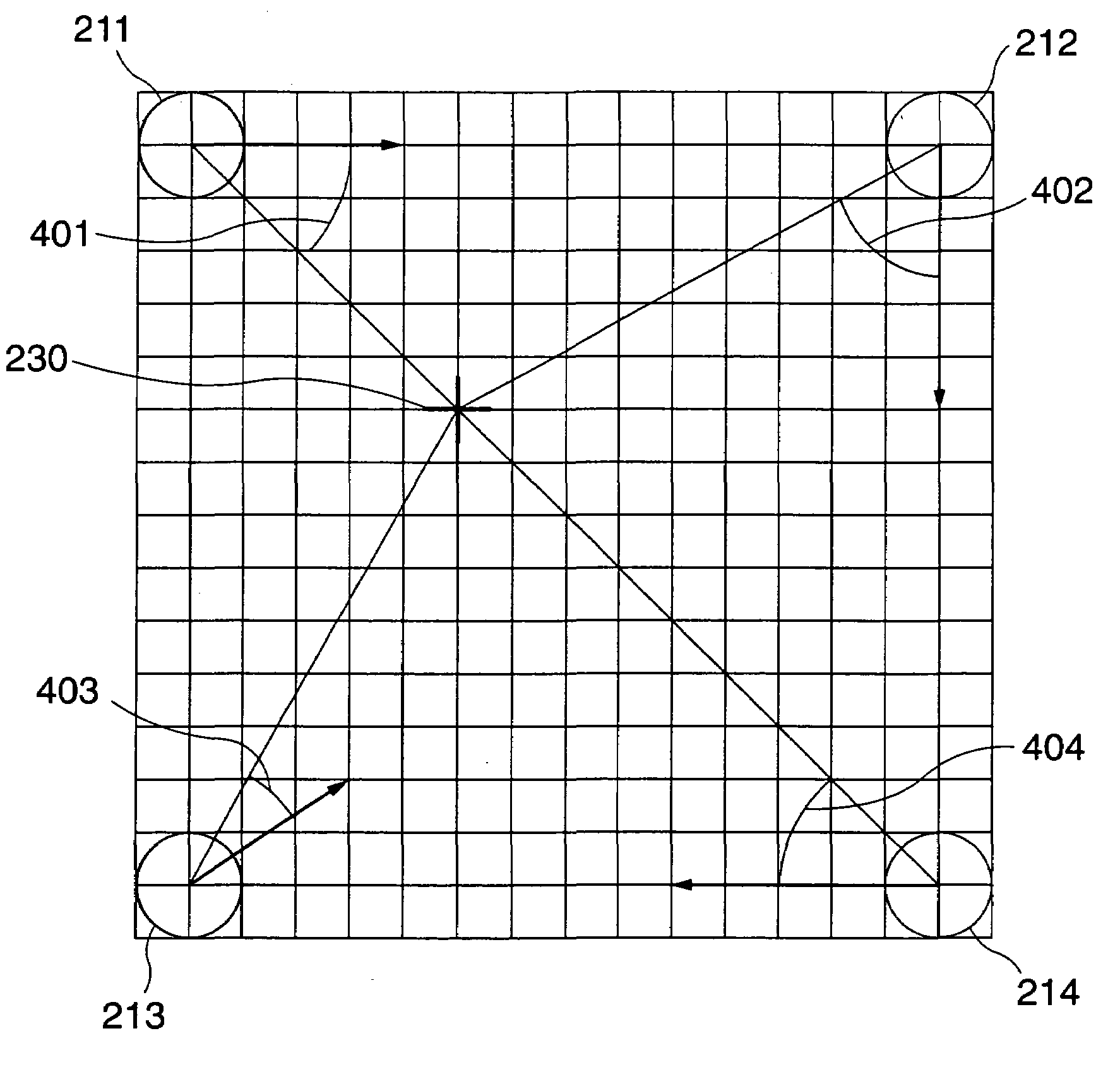
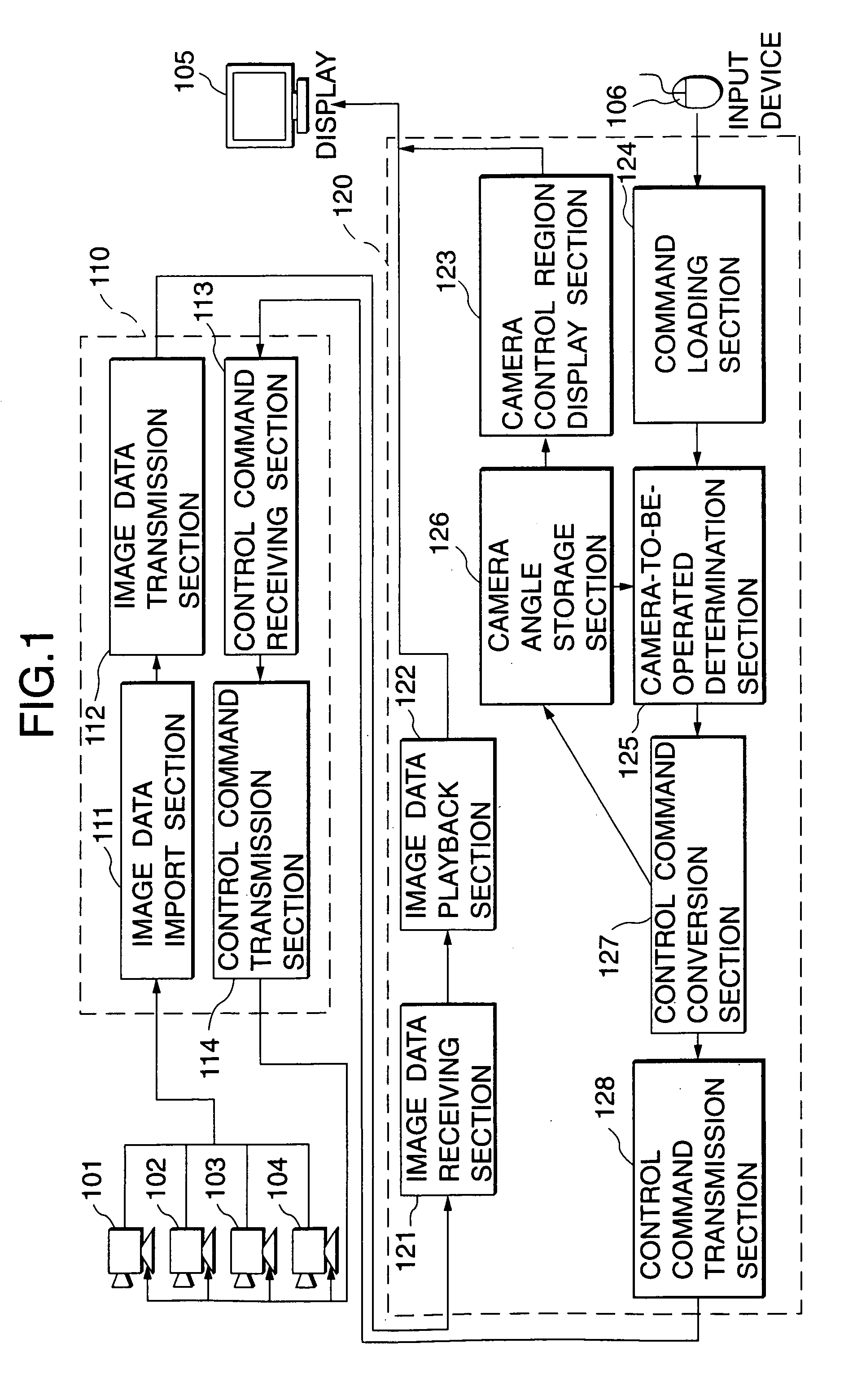
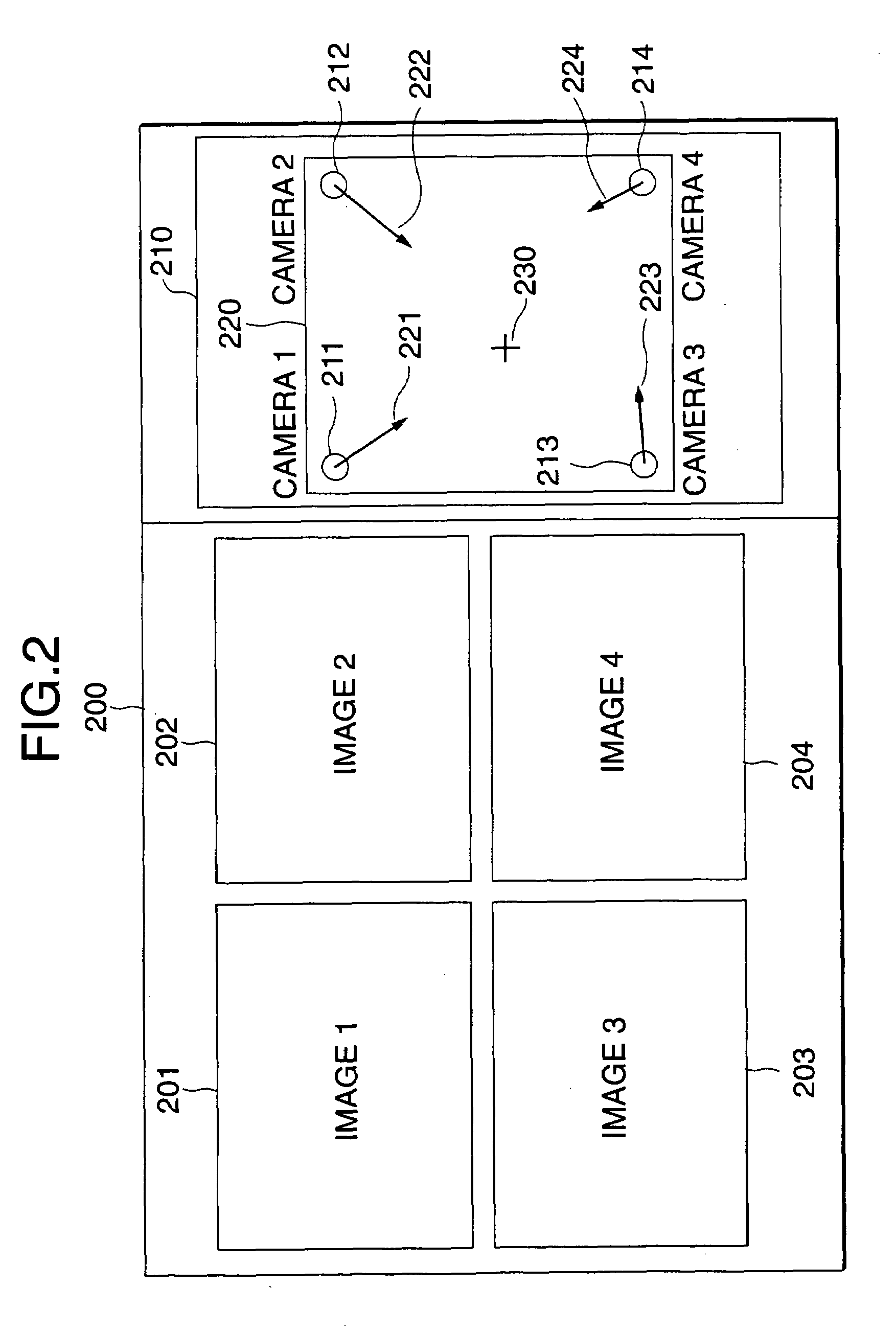
[0104]There will now be described a camera control method, under which, when an operator instructs a location which he desires to monitor (hereinafter called a “designated location”), by way of an input device connected to the image receiver, a camera capable of panning to and shooting the designated location most quickly is automatically selected from among the plurality of cameras, and the thus-selected camera is panned to the designated location. FIG. 1 shows the configuration of the system which embodies the camera control method. Further, FIG. 2 shows an example layout of a display screen connected to the image receiver in a case where came...

second embodiment

[0119]In example 1, on the basis of the camera angle information, the camera-to-be-operated determination section 125 determines, as a camera to be operated, the camera capable of most quickly panning toward a location designated by the operator, and produces a command used for actually panning the thus-determined camera. In the present example, there will be described a method of panning another camera rather than the thus-selected camera in the event of presence of an impediment along an imaginary extension between the camera and the designated location. FIG. 6 shows the configuration of a system embodying the method, and FIG. 7 shows an example impediment 701 on the map 220 provided in the camera control region 210 displayed on the screen 200 of the image receiver 120.

[0120]In FIG. 6, reference numerals 101, 102, 103, and 104 designate cameras; 110 designates an image transmitter for transmitting image data; 120 designates an image receiver for receiving the image data and playin...

third embodiment

[0135]In the first embodiemnt, the image receiver 120 selects a camera capable of panning toward the designated location most quickly, on the basis of the angles of the cameras. In the present example, two factors are employed as conditions for selecting a camera to be operated; that is, the angle and focus of a camera. In order enable comparison among cameras in terms of two factors of different scales; that is, between the angle and focus of the camera, these factors are converted into two factors capable of being compared; that is, the time required for the camera to pan toward the designated location, and the time required for the camera to attain a focus on the designated location. The configuration of a system embodying the method of the present invention is shown in FIG. 10.

[0136]The image receiver 120 of the present example corresponds to the image receiver of the first embodiment additionally provided with an angular-shift-time calculation section 1001 for calculating the t...


PUM


Abstract

A camera control apparatus and method, in that angles required for cameras to train on a position designated by an operator, are calculated from the designated position and directions in which the cameras are currently oriented. On the basis of the thus-calculated angles, a camera requiring the minimum angle from among the plurality of cameras is determined as the camera capable of being trained on the designated position most quickly.

Description

BACKGROUND OF THE INVENTION[0001]The present invention relates to an image-receiver (e.g., a camera control system capable of controlling a camera angle) of a system comprising an image-transmitter for transmitting camera images captured by a plurality of cameras whose angles can be controlled, and the image-receiver for displaying the thus-transmitted camera images.[0002]Recent advances made in network technology has brought out a system which transmits over a network an image captured by a camera and plays back the image at the receiving end (hereinafter often called an “image-receiving end”). Of such systems, many systems enable the image-receiving end which receives and plays back an image to control a turn table on which is mounted a camera connected to the transmitting end (hereinafter often called an “image-transmitting end”).[0003]Japanese Patent Unexamined Publication 7-123390 / (1995) describes a camera control system which enables an image-receiving end to control a camera ...

Claims


Application Information

Patent Timeline
Patent Type & Authority Patents(United States)
IPC IPC(8): H04N7/18H04N5/232
CPCH04N5/23203H04N7/181H04N23/66
Inventor OKADA, SUSUMUNANMA, EIMEINOJIMA, SHINJI
Owner PANASONIC INTELLECTUAL PROPERTY CORP OF AMERICA
Why Eureka
Try Eureka