
Methods and apparatus for cleaning a stencil

a stencil and cleaning method technology, applied in the direction of vehicle cleaning, manufacturing tools, vehicle maintenance, etc., can solve the problems of solvent paste being applied in inconsistent and uneven fashion, affecting the alignment procedure of the circuit board with the stencil, and inadvertently disposed of solvent paste on the unintended areas of the circuit board,

Active Publication Date: 2005-10-18
KPS SPECIAL SITUATIONS FUND II LP
View PDF7 Cites 39 Cited by
  • Summary
  • Abstract
  • Description
  • Claims
  • Application Information

AI Technical Summary

Benefits of technology

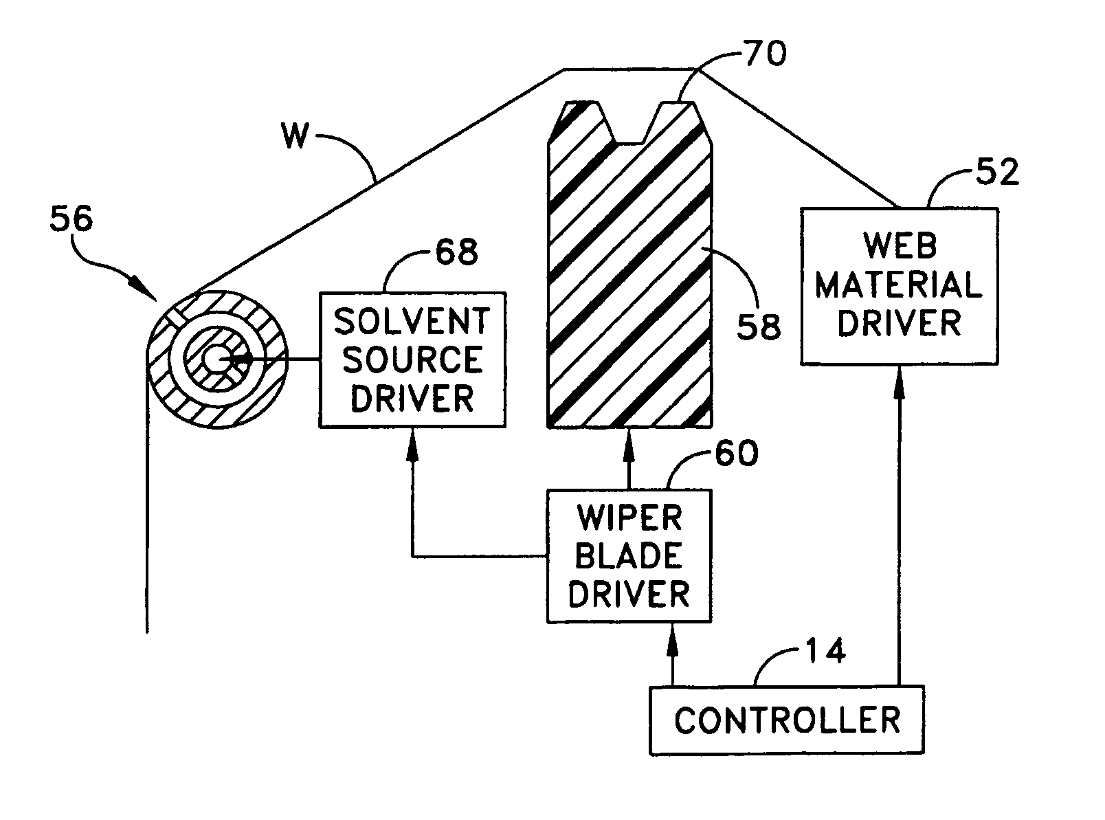
"The invention provides improvements to stencil cleaning apparatus. The first aspect is a stencil wiper apparatus that includes a material supply assembly and a fluid delivery assembly to wet the material. The apparatus also includes a wiper blade assembly to move the material between a first position and a second position. The method involves delivering a roll of material, evenly applying fluid on the material, and placing the material in a position proximate to the stencil. The technical effects of the invention include improved stencil cleaning efficiency and accuracy."

Problems solved by technology

This presents various problems, such as the solder paste being inadvertently disposed on the unintended areas of the circuit boards.
Also, as the solder paste hardens, it complicates the alignment procedure of a circuit board with the stencil.
A disadvantage to the system described in Doyle is that solvent may be applied to the paper in an inconsistent and uneven fashion.
Another result is that too much solvent may be delivered to the portion of paper close to the solvent source thereby resulting in an excessive amount of solvent being applied to the stencil.

Method used


Image

  • Methods and apparatus for cleaning a stencil
  • Methods and apparatus for cleaning a stencil
  • Methods and apparatus for cleaning a stencil

Examples


Embodiment Construction

[0024]This invention is not limited in its application to the details of construction and the arrangement of components set forth in the following description or illustrated in the drawings. The invention is capable of other embodiments and of being practiced or of being carried out in various ways. Also, the phraseology and terminology used herein is for the purpose of description and should not be regarded as limiting. The use of “including,”“comprising,”“having,”“containing,”“involving,” and variations thereof herein, is meant to encompass the items listed thereafter and equivalents thereof as well as additional items.

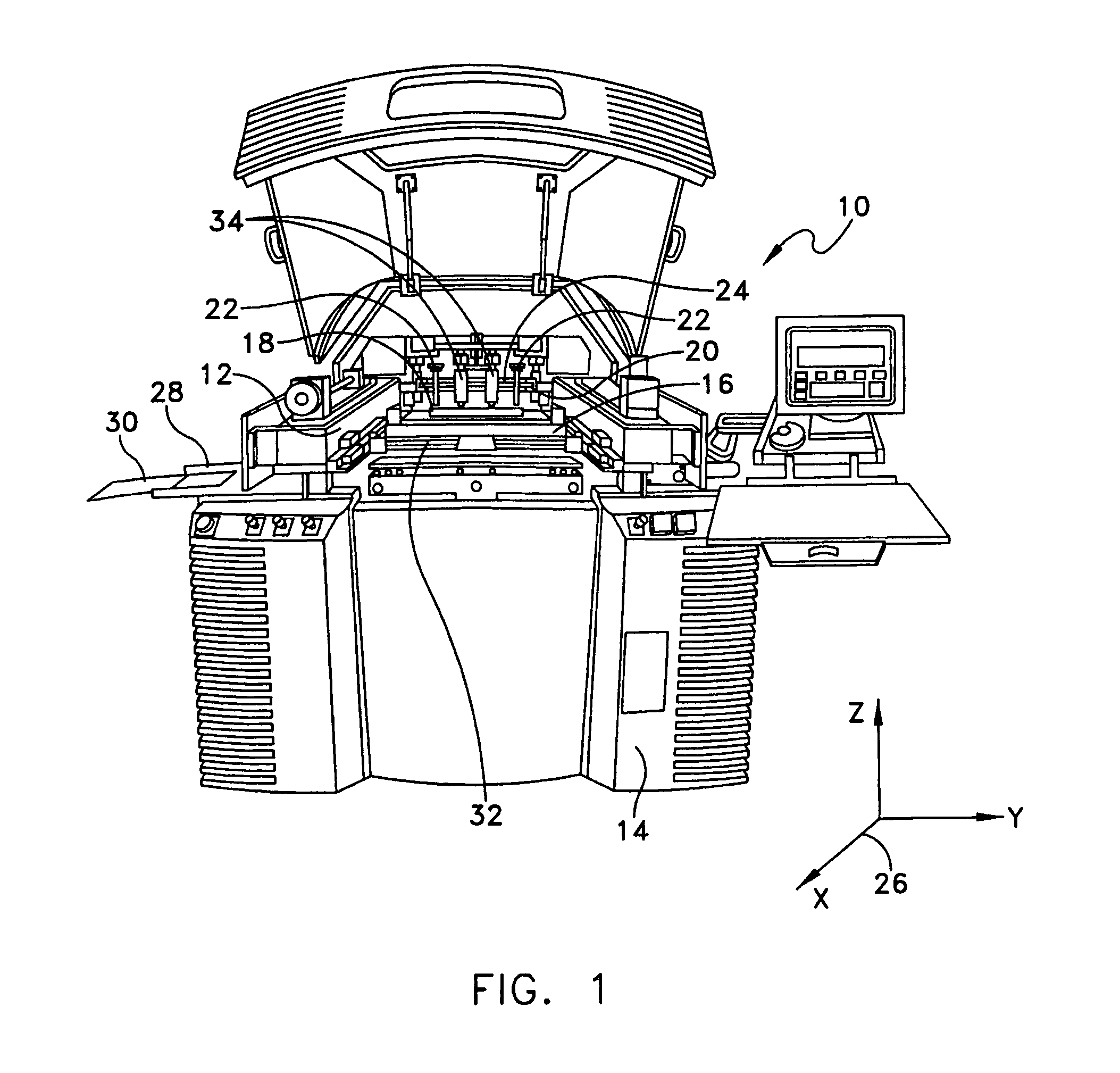
[0025]For purposes of illustration, embodiments of the present invention will now be described with reference to a stencil printer used to print solder paste onto a circuit board. One skilled in the art will appreciate, however, that embodiments of the present invention are not limited to stencil printers that print solder paste onto circuit boards, but rather, may ...


PUM

PropertyMeasurementUnit
lengthaaaaaaaaaa
widthaaaaaaaaaa
pressureaaaaaaaaaa

Abstract

A stencil wiper apparatus for wiping a stencil of a stencil printer includes a material supply assembly having a supply roller to deliver a roll of material, a take-up roller to receive the material, and a drive to move the material across the stencil between the supply roller and the take-up roller. The apparatus further includes a fluid delivery assembly to wet the material. The fluid delivery assembly includes an outer tube, an inner tube and a fluid delivery source. The outer tube is designed to engage the material and to deliver fluid to the material. The inner tube is positioned within the outer tube, and designed to deliver fluid to the outer tube. The fluid delivery source delivers fluid to the inner tube. A method for wiping a stencil of a printing machine is further disclosed.

Description

RELATED APPLICATIONS[0001]This application relates to U.S. patent application Ser. No. 10 / 784,121 entitled SELF-CONTAINED VACUUM MODULE FOR STENCIL WIPER ASSEMBLY by Joseph Perault and William Claiborne, filed on even date herewith, and U.S. patent application Ser. No. 10 / 784,122 entitled METHODS AND APPARATUS FOR CHANGING WEB MATERIAL IN A STENCIL PRINTER by Joseph Perault, Randy Peckham, Gary Freeman and Frank Marszalkowski, filed on even date herewith. Both of these related applications are incorporated herein by reference.BACKGROUND OF INVENTION[0002]1. Field of Invention[0003]The present invention relates generally to stencil cleaning methods and apparatus, and more particularly to a stencil cleaning apparatus that consistently and evenly applies a fluid, such as solvent, on a web material prior to the web material being placed in a position to clean the stencil.[0004]2. Discussion of Related Art[0005]In a typical surface-mount circuit board manufacturing operation, a stencil p...

Claims


Application Information

Patent Timeline
Patent Type & Authority Patents(United States)
IPC IPC(8): B41F35/00
CPCB41F35/005B41P2235/24B41F15/06B41F35/002H05K3/1216
Inventor PERAULT, JOSEPH A.CLAIBORNE, WILLIAM RUSSELL
Owner KPS SPECIAL SITUATIONS FUND II LP
Learn More