Engine cooling system

a cooling system and engine technology, applied in the direction of machines/engines, mechanical equipment, cylinders, etc., can solve the problems of increasing parasitic energy losses, slowing down the cooling process, etc., to reduce parasitic losses, increase or decrease the flow of coolant

Inactive Publication Date: 2005-10-18
GM GLOBAL TECH OPERATIONS LLC
View PDF11 Cites 99 Cited by
  • Summary
  • Abstract
  • Description
  • Claims
  • Application Information

AI Technical Summary

Benefits of technology

[0006]The present invention minimizes parasitic losses in a vehicle internal combustion engine cooling system, by using optionally a variable speed water pump and a diverter valve to selectively increase or decrease the flow of coolant through cooling jackets of the engine. In addition, the present invention may also cool the engine after the engine is shut down, by using an electric pump to circulate coolant and a reversible fan to control air flow in the engine compartment and through the heat exchanger.
[0011]Coolant is circulated through the system, preferably by a variable speed electric water pump. The flow of coolant is directed with a diverter valve connected between the pump and the engine. The diverter valve controls the flow of coolant through the head and the block. The pump determines the overall system flow rate while the diverter valve determines the direction of flow through the cooling jackets of the engine. Control of the flow of coolant with the pump and the diverter valve is optimized to increase engine efficiency.
[0012]Heat pipes can be installed at critical locations of the head such as at valve bridges or around the spark plugs to increase thermal conductivity of the head and carry more heat to the cooling jackets. As a result, the critical metal temperatures in the head are reduced and the amount of heat dissipated to the coolant is increased, thereby further increasing system efficiency.
[0015]After the engine is shut down, the controller continues to operate the water pump to maintain the flow of coolant through the engine. The controller may also reverse the direction of the heat exchanger fan to direct air from under the engine compartment through the heat exchanger and out of the engine compartment. This reduces the temperature of the air in the engine compartment and prevents air heated by the heat exchanger from being directed into the engine compartment.

Problems solved by technology

However, under severe conditions an engine requires increased coolant flow to maintain proper component temperature.
If a high flow rate water pump is used to provide a high coolant flow rate under severe conditions to prevent engine overheating, the amount of coolant flow will be excessive under normal operating conditions, resulting in parasitic energy losses.
The lack of coolant circulation after an engine stops allows engine heat to soak into the coolant which remains in the engine and slows the cooling process.

Method used


Image

  • Engine cooling system
  • Engine cooling system
  • Engine cooling system

Examples


Embodiment Construction

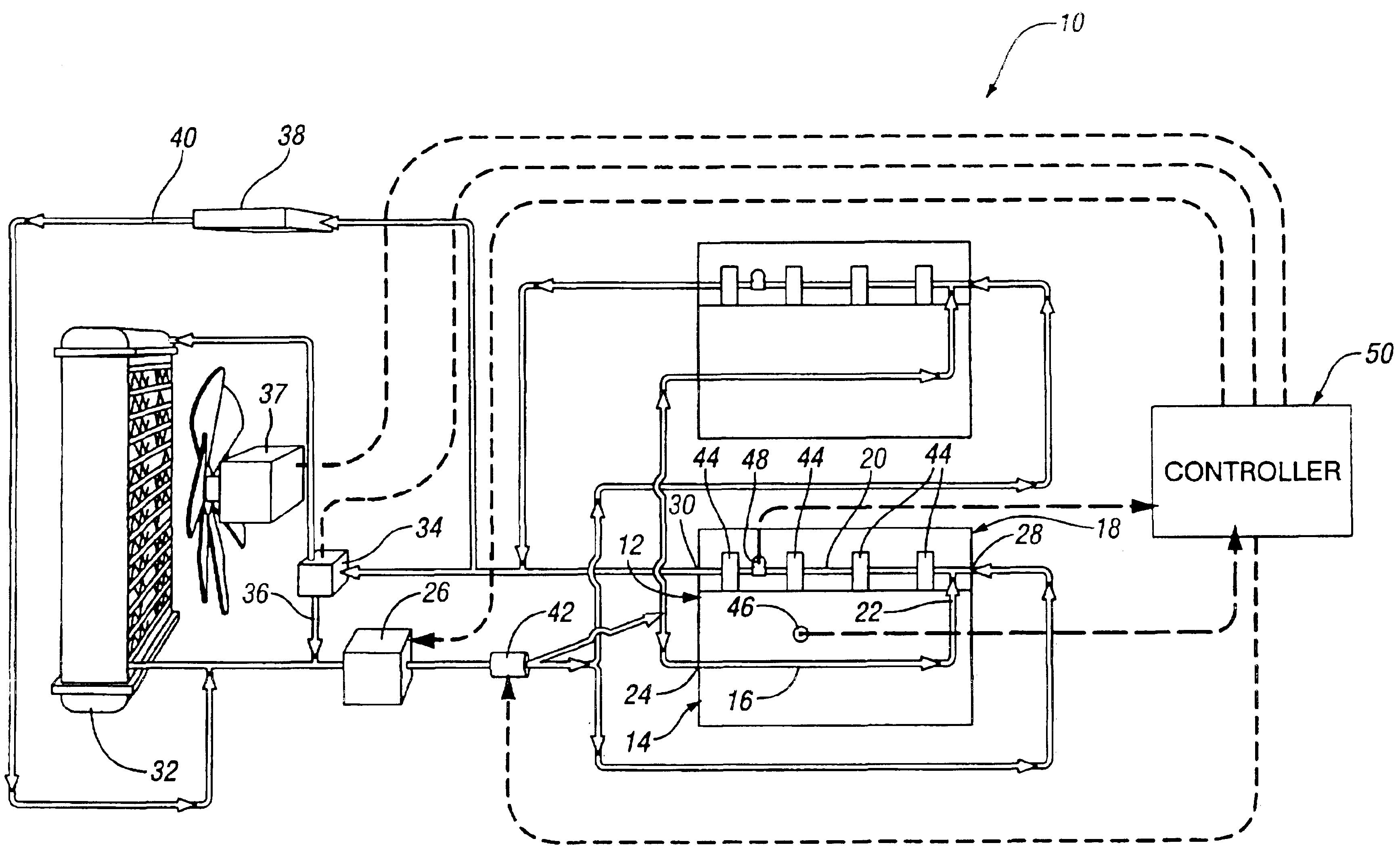
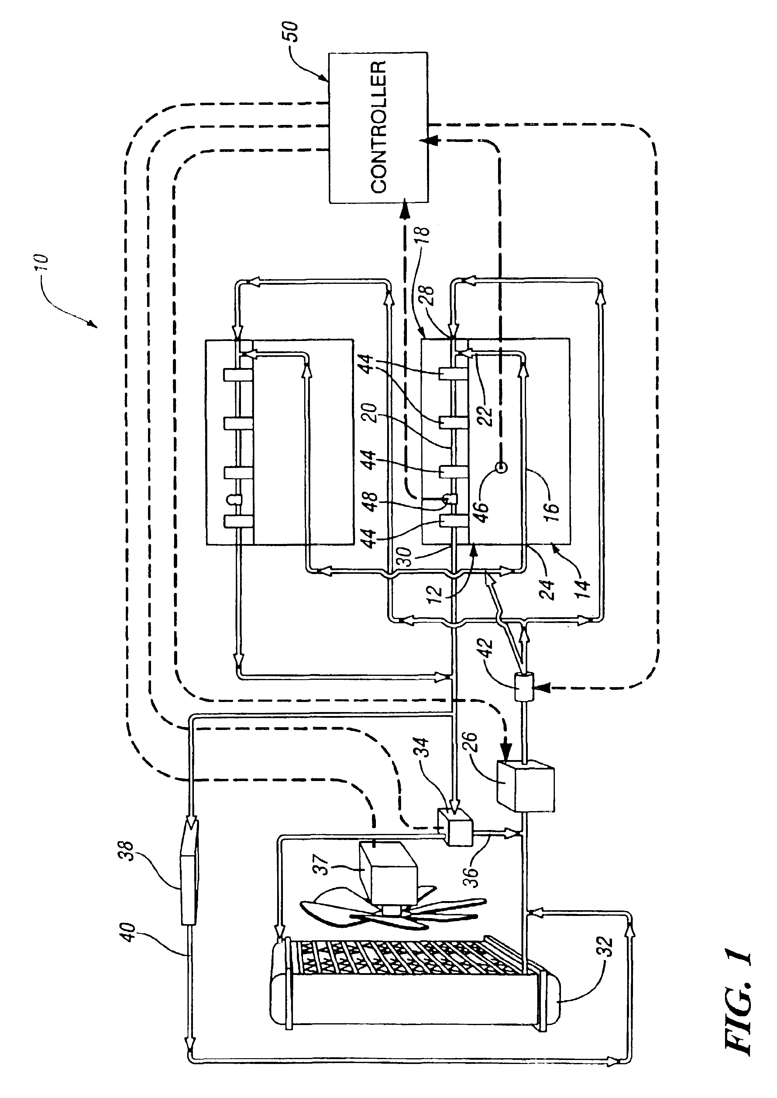
[0019]Referring to FIG. 1 of the drawings in detail, numeral 10 generally indicates a cooling system for an internal combustion engine. System 10 includes an engine 12 having a cylinder block 14 with a cooling jacket 16 and a cylinder head 18 mounted on the cylinder block with a cooling jacket 20. Cooling jackets 16 and 20 are connected by an internal passage 22 between the head 18 and the block 14. A first coolant inlet 24 connects with the cooling jacket 16 of the block 14 and receives coolant from a water pump 26. A second coolant inlet 28 connects with the cooling jacket 20 of the head 18 and also may receive coolant from the water pump 26.

[0020]A coolant outlet 30 connects with the cooling jacket 20 of the head 18 and discharges coolant to an ambient air heat exchanger 32 through a temperature control valve 34. The ambient air heat exchanger 32 removes excess heat from the coolant heated in the engine 12. Coolant discharged from the heat exchanger 32 is conducted back to the wa...


PUM


Abstract

A cooling system has a diverter valve to selectively control the flow of coolant through an internal combustion engine having a cylinder block with a cooling jacket and a cylinder head mounted on the block with a cooling jacket. A controller, responsive to the temperature of the block and the head, controls the diverter valve and a water pump to provide adequate coolant flow through the head and the block as needed to maintain optimal operating temperatures. After the engine is shut off, the controller continues to operate the water pump and a cooling fan to continue to cool the engine for a period of time.

Description

TECHNICAL FIELD[0001]This invention relates to a cooling system for a liquid cooled internal combustion engine and, more particularly, to a method and means for controlling liquid coolant flow through the system.BACKGROUND OF THE INVENTION[0002]An internal combustion engine commonly employs a pressurized cooling system with a circulating liquid coolant for cooling the engine. Engine heat is transferred from the engine to the coolant in a cooling jacket surrounding combustion heated parts of the engine. The heat absorbed by the circulated coolant is generally dissipated by a heat exchanger into the air.[0003]Under normal operating conditions, an engine may require only nominal coolant flow to maintain proper temperature of internal components. However, under severe conditions an engine requires increased coolant flow to maintain proper component temperature. If a high flow rate water pump is used to provide a high coolant flow rate under severe conditions to prevent engine overheatin...

Claims


Application Information

Patent Timeline
Patent Type & Authority Patents(United States)
IPC IPC(8): F01P7/16F01P7/14F01P7/04F01P7/00F01P3/02
CPCF01P7/165F01P3/02F01P7/044F01P2003/021F01P2003/024F01P2003/027F01P2003/028F01P2007/146F01P2025/31F01P2025/33F01P2031/30F01P2060/08
Inventor SANTANAM, CHANDRAN B.RIZOULIS, DIMITRIOSMANIAM, BALAJIMANDRUSIAK, GARY D.
Owner GM GLOBAL TECH OPERATIONS LLC
Why Eureka
Try Eureka