Membrane module

a membrane module and fiber technology, applied in the field of hollow fiber membrane modules, can solve the problems of increasing the amount of membrane used, increasing the operating cost of the module, increasing the lumen and shell side pressure, etc., and reducing the diameter and packing fraction of the module, reducing the amount of fiber within the tubesheet, and increasing the wind angle

Active Publication Date: 2011-08-16
POROUS MEDIA CORP
View PDF9 Cites 15 Cited by
  • Summary
  • Abstract
  • Description
  • Claims
  • Application Information

AI Technical Summary

Benefits of technology

Additionally, in our module design we are not limited by the wind angle as indicated by Bikson U.S. Pat. No. 4,881,955 at col. 8, lines 53-60. In all of the prior art relating to helically wound modules, the wind angle in the active area region is constant within a layer of fibers in going from one end of the bundle to the other. With a low wind angle maintained in the tubesheet area, this would result in a significant amount of inactive fiber in the tubesheet, which adds to the amount of membrane used, an increase in capital cost of the module, and adds to the lumen and shell side pressure drops and an increase in the operating cost of the module. Additionally this reduces the tubesheet strength and would then require a larger tubesheet dimension, further increasing the membrane requirement and cost.
In the present invention, we increase the wind angle near the tubesheet region (not decrease it such as in Giglia U.S. Pat. No. 5,837,033) such that the fiber enters the tubesheet more parallel to the core, and with a greatly decreased module diameter and packing fraction near the tubesheet. This feature reduces the amount of fiber within the tubesheet, reduces the pressure drop, and minimizes the parasitic loss of tubesheet integrity as a result of the presence of the fiber.
A further improvement that this increase in wind angle provides is an improved penetration of the shell side gas into the fiber bundle. For a given number of fibers, the packing fraction and bed depth in the vicinity of this wind angle increase is significantly lower that in the adjacent areas. This allows for more effective penetration of the shell side gas around all the fibers and into the bundle.
It was also found that in the external sweep module, as in the internal sweep module, as discussed hereinabove, the increase in wind angle provides an improved penetration of the sweep gas into the fiber bundle. For a given number of fibers, the packing fraction and bed depth in the vicinity of this wind angle increase is significantly lower that in the adjacent areas. This allows for more effective penetration of the sweep gas around all the fibers and into the bundle. For the impervious wrap, we do not embed it in either tubesheet, but rather, create a seal between the wrap and the shell using the methods described above.

Problems solved by technology

With a low wind angle maintained in the tubesheet area, this would result in a significant amount of inactive fiber in the tubesheet, which adds to the amount of membrane used, an increase in capital cost of the module, and adds to the lumen and shell side pressure drops and an increase in the operating cost of the module.
Additionally this reduces the tubesheet strength and would then require a larger tubesheet dimension, further increasing the membrane requirement and cost.

Method used


Image

  • Membrane module
  • Membrane module
  • Membrane module

Examples


Embodiment Construction

Helically wound bore-side feed internal sweep membrane air dryer modules were manufactured according to the parameters in the Table 1. The hollow fibers used were manufactured using the dry-wet phase inversion process. Water, a coagulant, was used as the bore fluid and a polymer solution containing solvent and non-solvent was pumped into the annulus of the hollow fiber spinneret. The fiber was processed according to procedures known in the art and then used to manufacture the modules. The resulting asymmetric porous hollow fiber was then coated on its inner diameter with a hydrophilic polymer.

TABLE 1Module Design ParametersAverageStandardLengthActive LengthDeviation inActive SurfaceVariation(cm)Length (cm)Area (cm2)Module A13%172.26.051874Module B70%171.829.41878

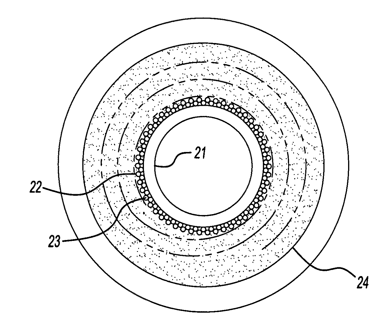
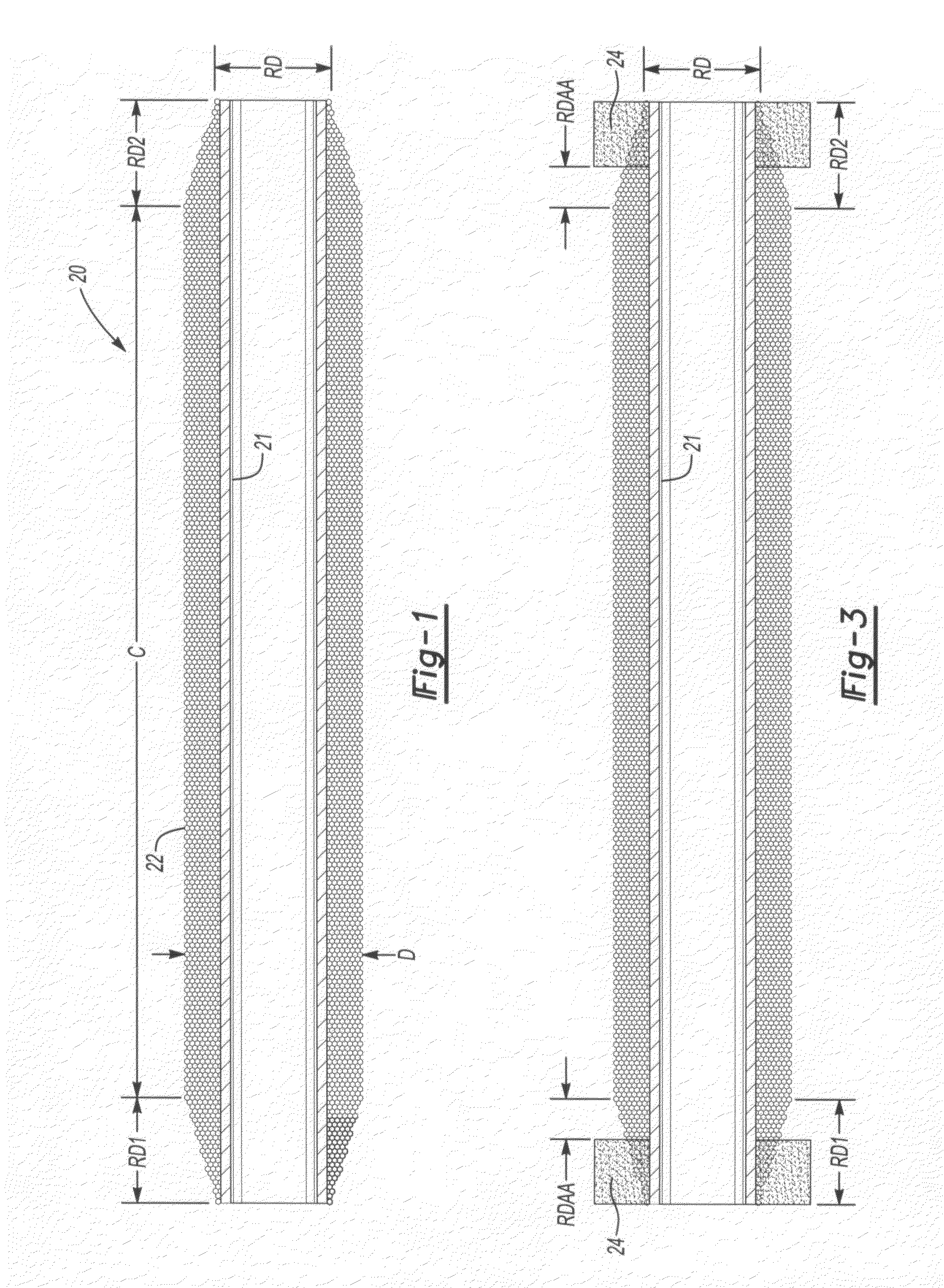
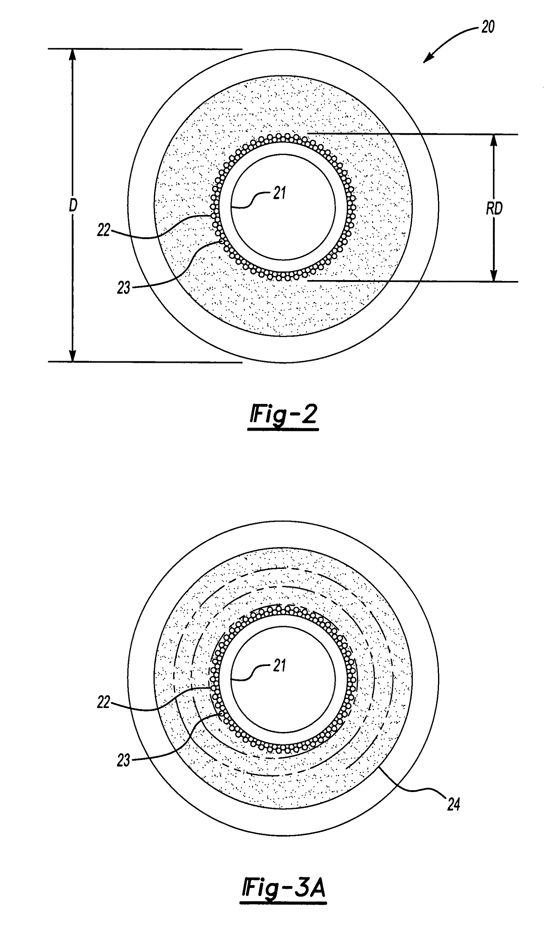
During this winding process, a cylindrical core was used and the angle at which the fiber was laid down was increased in the vicinity of the tubesheet region on each end of the module such that the diameter of the fiber bund...


PUM

PropertyMeasurementUnit
pressuresaaaaaaaaaa
surface areaaaaaaaaaaa
diameteraaaaaaaaaa

Abstract

A helically wound hollow membrane module having a core with a plurality of helically wound layers of semi-permeable hollow fibers wound on the core. The fiber wind angle with respect to any one layer of fibers may be essentially constant along the axial length of the module, except in one or both end or tubesheet regions, where the wind angle may be increased, in at least some of the layers relative to the essentially constant wind angle, to produce an area of decreasing diameter.

Description

TECHNICAL FIELD OF THE INVENTIONThis invention generally relates to hollow fiber membrane modules for the use in gas separation or gas transfer, more specifically to an improved module design for the removal of water vapor from gas streams or for the transfer of water vapor from one gas stream to a second one.BACKGROUND OF THE INVENTIONWater-permeable hollow fiber membrane modules have been used commercially for the dehydration of gas streams as well as for the transfer of moisture from one gas stream to another. U.S. Pat. Nos. 6,585,808 and 6,616,735 disclose membrane modules suitable for gas dehydration and are incorporated herein as references and U.S. Pat. No. 6,779,522 discloses a membrane for drying or humidifying gases. For the purpose of describing the salient features of this invention, only bore-side feed gas dehydration modules will be considered, although the membrane module design concepts are applicable to the gas separation and gas transfer applications mentioned prev...

Claims


Application Information

Patent Timeline
Patent Type & Authority Patents(United States)
IPC IPC(8): B01D53/22
CPCB01D53/228B01D53/268B01D63/021B01D65/003B01D63/025B01D2313/23B01D2257/80B01D2311/13B01D63/0233
Inventor BURBAN, JOHN HENRYBERG, JEFFREY WILLIAMSTEFFENSMEIER, BRENT JOSEPHTUMA, JOSEPH CHARLESGEISZ, CARL MATTHEWCUTA, CRAIG JONATHAN
Owner POROUS MEDIA CORP
Why Eureka
Try Eureka