Methods and devices for providing power to network-based systems

a network-based system and power supply technology, applied in power distribution line transmission, process and machine control, instruments, etc., can solve the problems of too complicated to place power on the same wire as data, not always the best way to provide power,

Active Publication Date: 2005-10-18
MICROSOFT CORP
View PDF5 Cites 32 Cited by
  • Summary
  • Abstract
  • Description
  • Claims
  • Application Information

AI Technical Summary

Problems solved by technology

Separate from the type of information these systems will handle is the issue of how to provide power to them.
As is known in the art, this is not alway

Method used


Image

  • Methods and devices for providing power to network-based systems
  • Methods and devices for providing power to network-based systems
  • Methods and devices for providing power to network-based systems

Examples


Embodiment Construction

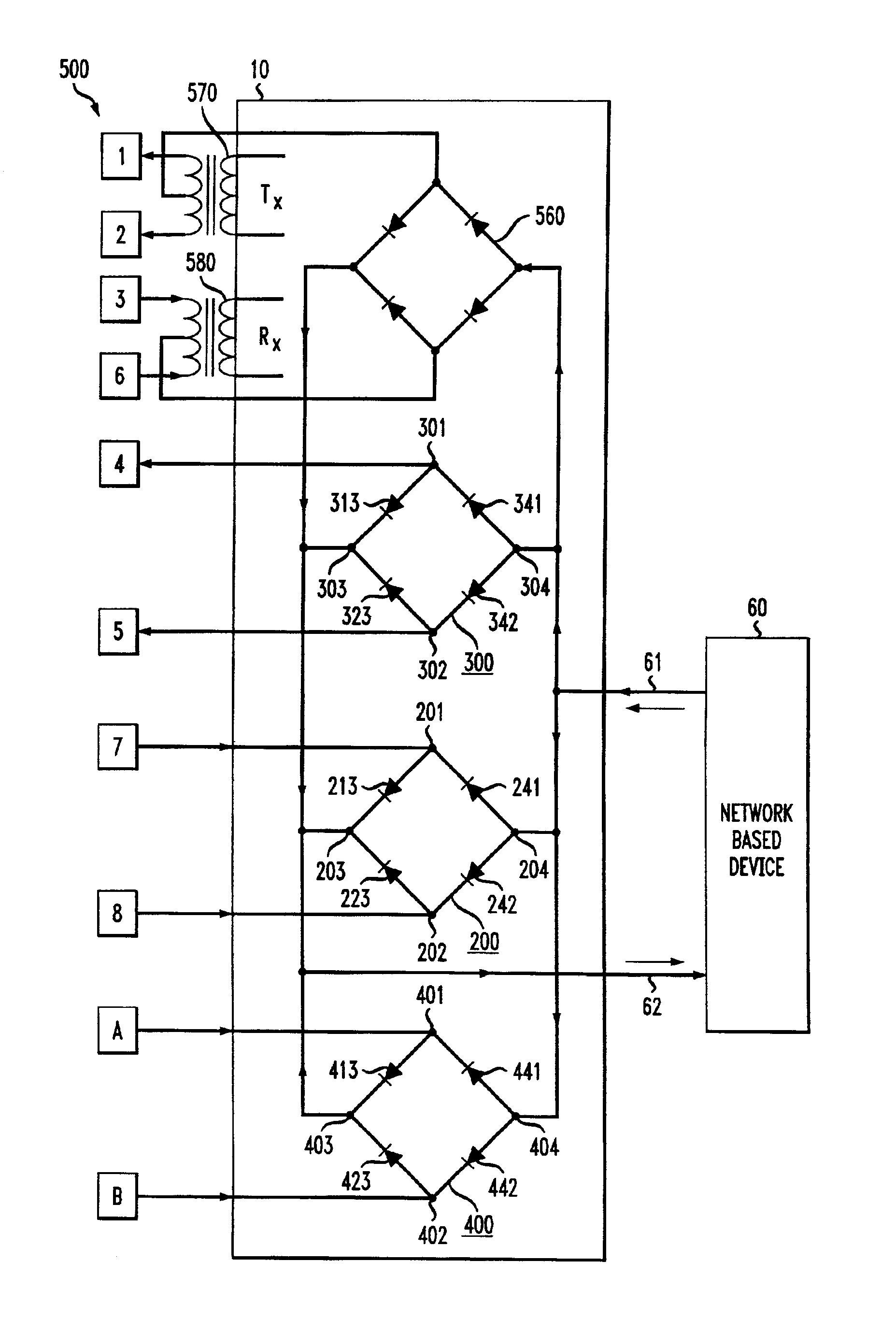
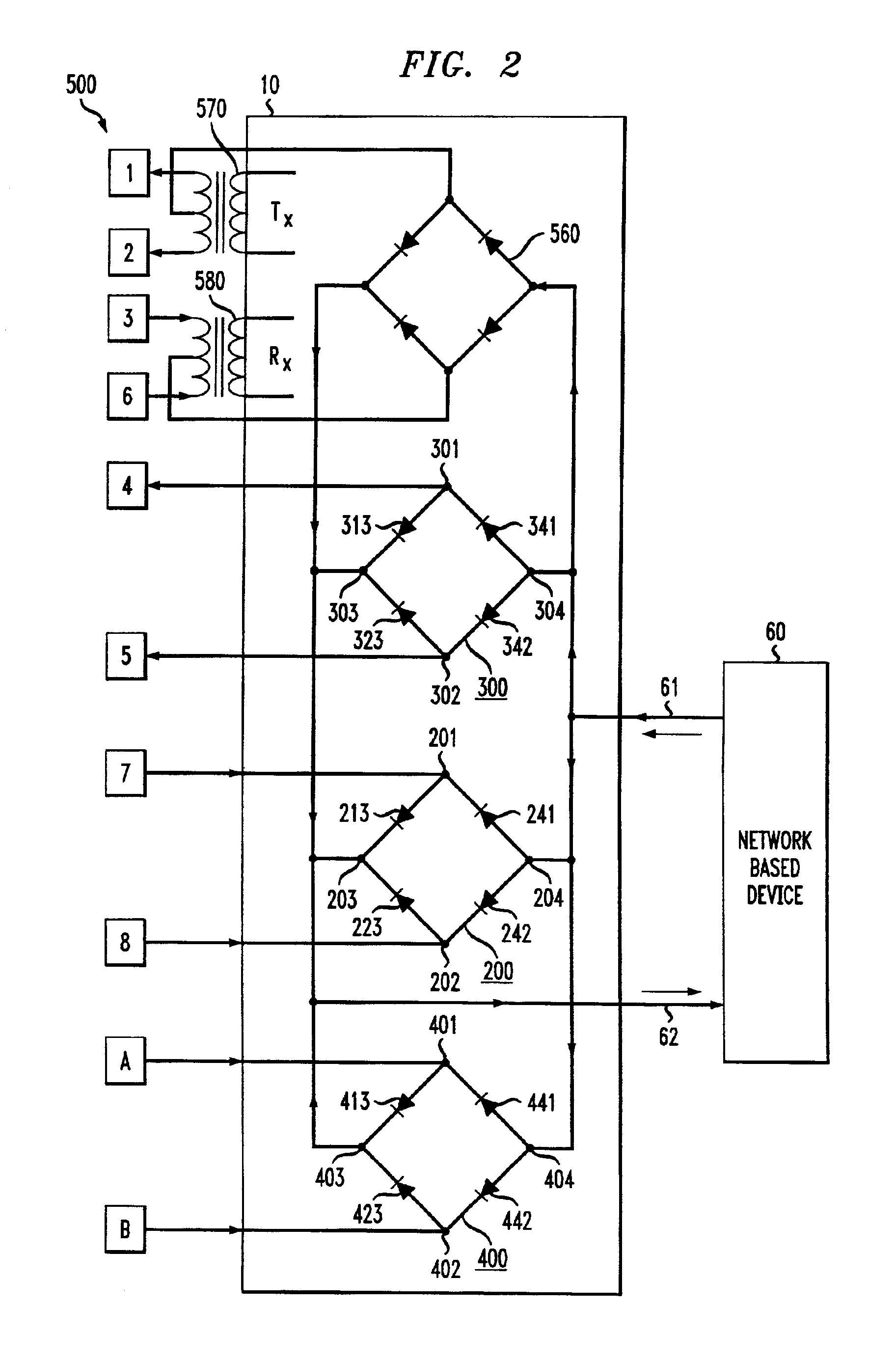
[0016]Referring to FIG. 1, there is shown a device 10 for providing power to a network-based device 60 according to one embodiment of the present invention. The device 60 may comprise any number of devices which are commonly connected to a network, (e.g., LANs), such as an IP-telephone or a computer.

[0017]As shown, the device 10 comprises four circuits, 20,30,40 and 50. For the sake of clarity, they will be referred to as a first circuit 20, second circuit 30, third circuit 40 and fourth circuit 50, respectively. All four circuits are designed to provide power to the system 60 via pathways 61 and 62.

[0018]According to one embodiment of the present invention, the third circuit 40 is adapted to provide “local power” to the network device 60 (e.g., from a wall unit connected to an electrical outlet or the like). The letters “A” and “B” indicate inputs into the third circuit 40. These inputs may take the form of terminals and / or pathways (e.g., an electrical cord). The fourth circuit 50...


PUM


Abstract

Circuits provide power to network-based devices, such as IP telephones, using spare conductors within existing LAN cables. The circuits, which may comprise diode bridges, are designed to provide power using existing and planned industry guidelines.

Description

BACKGROUND OF THE INVENTION[0001]It used to be that the network which controlled your telephone was different than the network which controlled your computer. In the not-too-distant future, these two networks will become one. For example, so-called “IP telephones” (short for “Internet-Protocol telephones”) will be able to function much like conventional telephones, albeit using unconventional means. That is, IP telephones and other network-based systems will be connected to a network capable of sending and receiving both voice, data and other signals (i.e., video) as Internet-Protocol signals.[0002]Separate from the type of information these systems will handle is the issue of how to provide power to them.[0003]One way to provide power is to use an electrical outlet. This connects a system to the electric company's power grid. A second method is to provide power using the same physical conductors (e.g., wires) which handle voice or data information. That is, power supplied by the ne...

Claims


Application Information

Patent Timeline
IPC IPC(8): H02J1/06
CPCH02J1/06
Inventor JETZT, JOHN J.
Owner MICROSOFT CORP
Why Eureka
Try Eureka