[0020]Accordingly, an
advantage of the present invention provides a driving circuit and a method of driving an organic electroluminescent device having the capability of shortening a time required to display picture data on a screen if the picture data is supplied from a
current driver integrated circuit and is of a minimum gray level.
[0021]Additional features and advantages of the invention will be set forth in the description that follows, and in part will be apparent from the description, or may be learned by practice of the invention. Other advantages of the invention will be realized and attained by the structure particularly pointed out in the written description and claims hereof as well as the appended drawings.
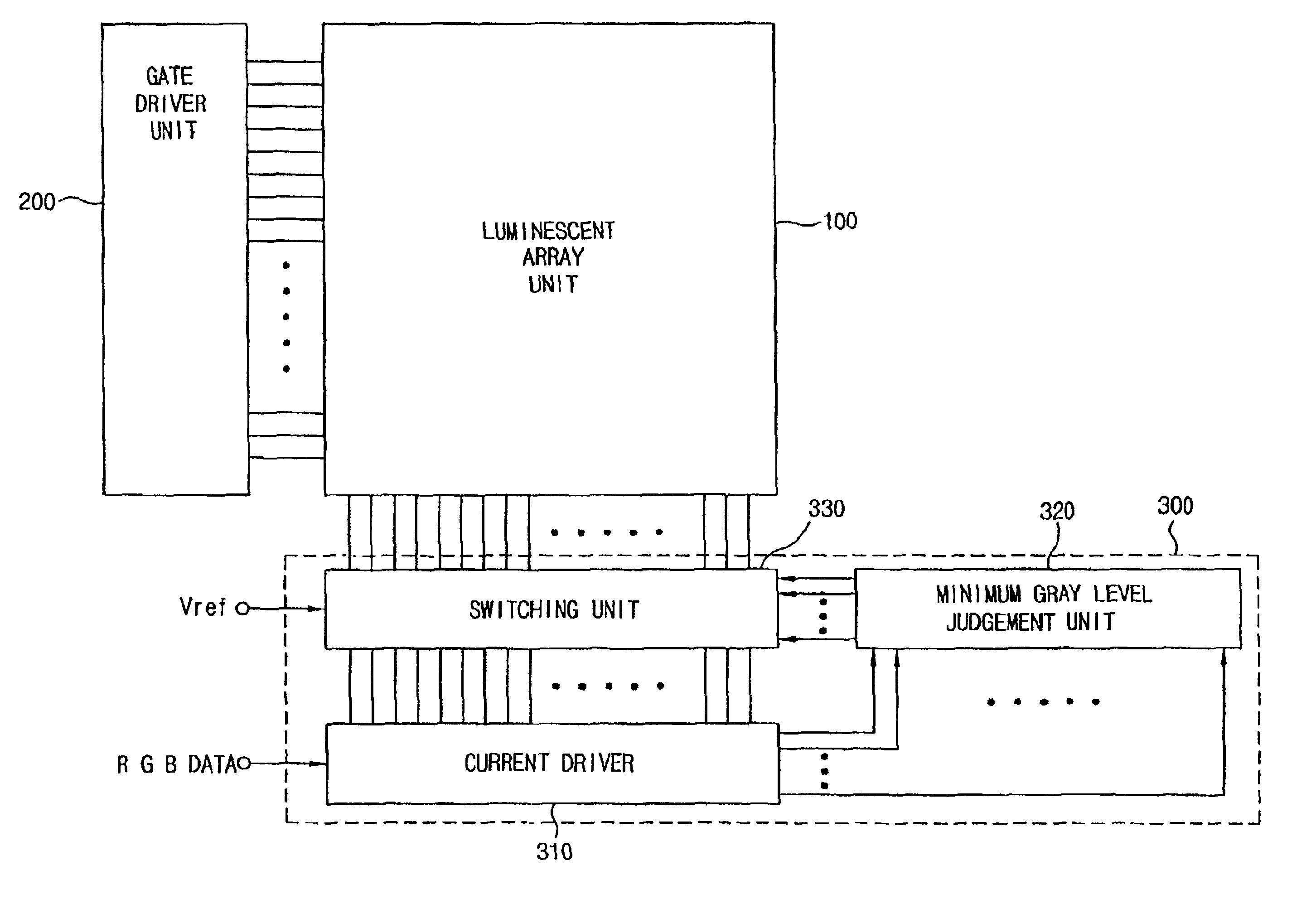
[0022]To achieve these and other advantages and in accordance with the purpose of the present invention, as embodied and broadly described herein, there is provided an organic electroluminescent device driving circuit having a
gate driver unit for sequentially outputting a
control signal to select gate lines in a luminescent array unit and a current driver unit for supplying picture data to
data lines in the luminescent array unit corresponding to gate lines that are selected by the gate driver unit and, therefore, driving organic electroluminescent devices connected to the selected line. The driving circuit includes a minimum gray level judgment unit for determining whether the picture
data applied from the current driver unit to a specific organic electroluminescent device within the luminescent array unit is of a predetermined minimum gray level; and a switching unit for receiving a control
signal dependent on the determination by the minimum gray level judgment unit and for selectively supplying (e.g., turning on and / or turning off) a reference
voltage to the selected organic electroluminescent device.
[0023]To achieve these and other advantages and in accordance with the purpose of the present invention, as embodied and broadly described, there is also provided an organic electroluminescent device driving circuit including a gate driver unit for sequentially outputting a control
signal to select gate lines in a luminescent array unit and a current driver unit for supplying picture data to
data lines in the luminescent array unit corresponding to gate lines that are selected by the gate driver unit and selectively driving organic electroluminescent devices connected the selected line. The driving circuit includes a minimum gray level judgment unit for determining whether the picture
data applied from the current driver unit to a specific organic electroluminescent device within the luminescent array unit is of a minimum gray level; and a switching unit for receiving a control
signal dependent on the determination by the minimum gray level judgment unit and for selectively supplying (e.g., turning on and / or turning off) a
reference current to the specific organic electroluminescent device.
[0024]To achieve these and other advantages and in accordance with the purpose of the present invention, as embodied and broadly described, there is provided an organic electroluminescent device driving method including the steps of reading picture data supplied to a plurality of organic electroluminescent devices within a luminescent array unit that are selected by a gate driver unit and a current driver unit; determining whether the read picture data is of a minimum gray level; and using the picture data to drive the organic electroluminescent devices with the current driver unit wherein the current driver unit supplies current to predetermined organic electroluminescent devices if the picture data is not of the minimum gray level, and wherein the current driver unit cuts off the current supplied to the predetermined organic electroluminescent devices if the picture data is of the minimum gray level. Accordingly, if the picture data is of the minimum gray level, a reference
voltage is supplied to the predetermined organic electroluminescent devices.
[0025]To achieve the above advantages, there is provided an organic electroluminescent device driving method including the steps of reading picture data supplied to a plurality of organic electroluminescent devices within a luminescent array unit that are selected by a gate driver unit and a current driver unit; determining whether the read picture data is of a minimum gray level; and using the picture data to drive the organic electroluminescent devices with the current driver unit, wherein the current driver unit supplies current to predetermined organic electroluminescent devices if the picture data is not of the minimum gray level, and wherein the current driver unit cuts off the current supplied to the predetermined organic electroluminescent devices if the picture data is of the minimum gray level. Accordingly, if the picture data is of the minimum gray level, a
reference current is supplied to the predetermined organic electroluminescent devices.

