Gridless IC layout and method and apparatus for generating such a layout

a gridless ic and layout technology, applied in the direction of photomechanical treatment originals, instruments, nuclear engineering, etc., can solve the problems of routers not typically exploring diagonal routing paths consistently, ic designs often penalize non-preferred-direction wiring on a layer, and arbitrarily limit the locations of interconnect lines

Inactive Publication Date: 2005-10-18
CADENCE DESIGN SYST INC
View PDF145 Cites 35 Cited by
  • Summary
  • Abstract
  • Description
  • Claims
  • Application Information

AI Technical Summary

Problems solved by technology

IC designs often penalize non-preferred-direction wiring on a layer.
While some commercial routers today might allow an occasional diagonal jog, these routers do not typically explore diagonal routing paths consistently when they are specifying the routing geometries of the interconnect lines.
Consequently, they arbitrarily limit the locations of interconnect lines and impose arbitrary spacing between the items in the layout.
These arbitrary limits increase the size and efficiency of a design.
Such IC layouts and IC's do not efficiently use the available spacing on the interconnect layers, and this adversely affects the size and efficiency of the layouts and the IC's.

Method used


Image

  • Gridless IC layout and method and apparatus for generating such a layout
  • Gridless IC layout and method and apparatus for generating such a layout
  • Gridless IC layout and method and apparatus for generating such a layout

Examples


Embodiment Construction

[0085]In the following description, numerous details are set forth for purpose of explanation. However, one of ordinary skill in the art will realize that the invention may be practiced without the use of these specific details. In other instances, well-known structures and devices are shown in block diagram form in order not to obscure the description of the invention with unnecessary detail.

I. Non-Preferred Direction Architecture

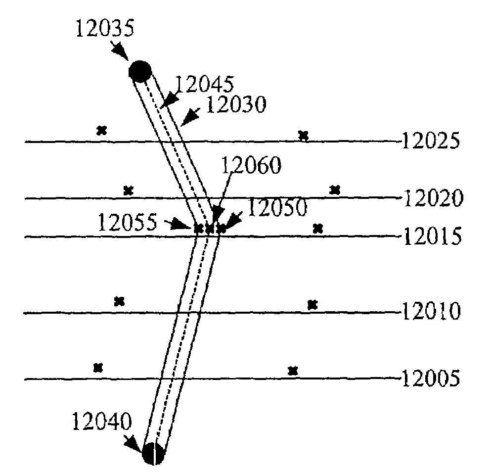
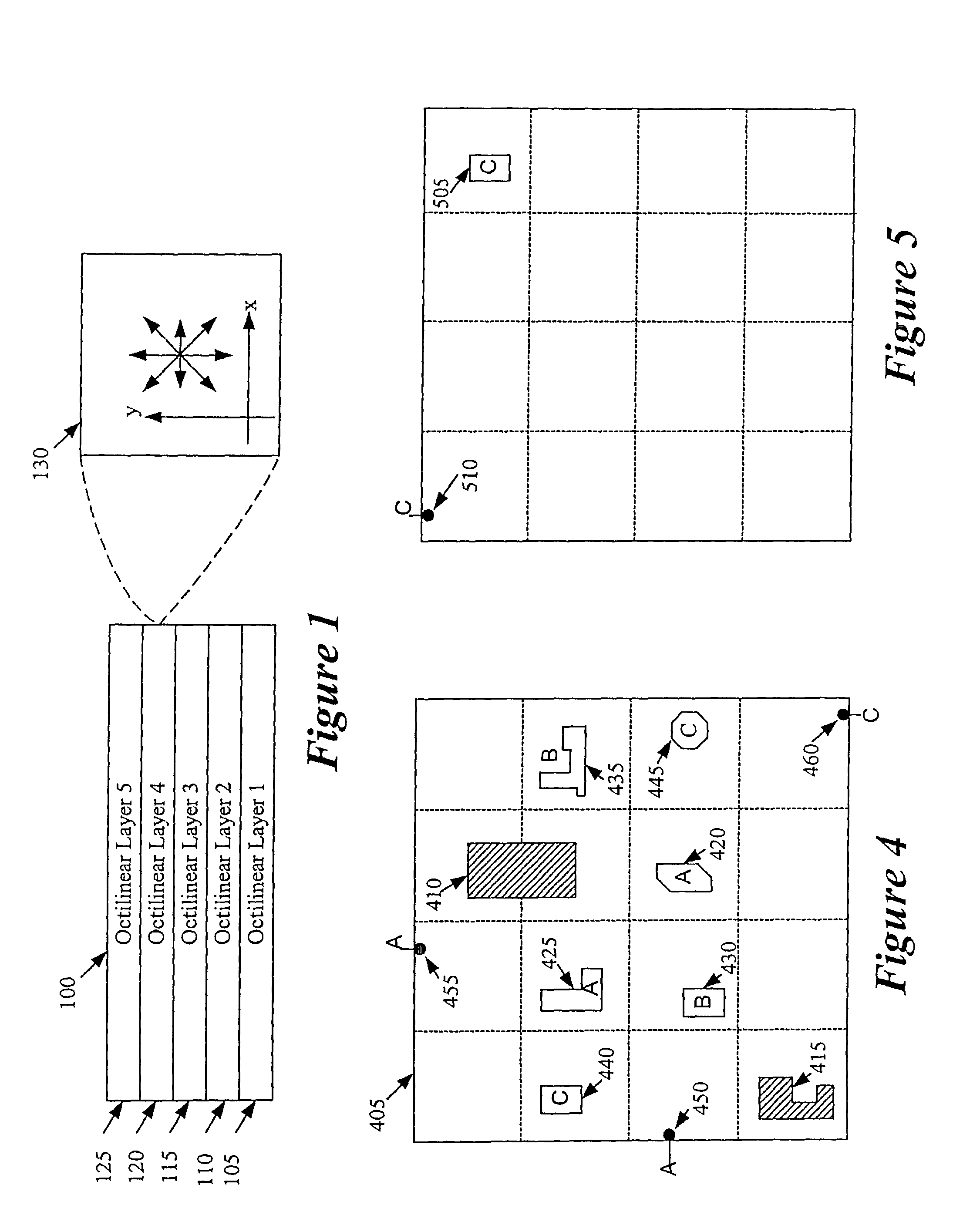
[0086]Some embodiments of the invention utilize non-preferred-direction (“NPD”) wiring models for designing IC layouts. An NPD wiring model has at least one NPD interconnect layer that has more than one preferred routing direction. Specifically, in such a wiring model, each NPD interconnect layer has at least two wiring directions that are equally preferable with respect to one another, and that are as preferable as or more preferable than the other wiring directions on that layer.

[0087]An NPD router that uses an NPD wiring model generates IC layouts with ...


PUM

PropertyMeasurementUnit
angleaaaaaaaaaa
angleaaaaaaaaaa
angleaaaaaaaaaa

Abstract

Some embodiments of the invention provide a method of routing nets in a region of an integrated-circuit (“IC”) layout. The method selects a net that has several routable elements. It then defines a route for the net. To define the route, the method uses a wiring model that specifies preferred non-Manhattan wiring directions. It also uses a manufacturing grid as the only grid for constraining the location of interconnect lines for connecting the net's routable elements.

Description

CLAIM OF BENEFIT TO PRIOR APPLICATIONS[0001]This patent application is a continuation of U.S. patent application Ser. No. 10 / 215,563, filed Aug. 9, 2002, which is incorporated herein by reference. This application is also a continuation-in-part of U.S. patent application Ser. No. 09 / 681,775, now U.S. Pat. No. 6,711,727, filed Jun. 3, 2001. This application further claims the benefit of U.S. Provisional Patent Application 60 / 396,571, filed Jul. 15, 2002; U.S. Provisional Patent Application 60 / 388,518, filed Jun. 12, 2002; U.S. Provisional Patent Application 60 / 385,975, filed Jun. 4, 2002; U.S. Provisional Patent Application 60 / 351,459, filed Jan. 22, 2002. This application is also a continuation-in-part of U.S. patent application Ser. No. 10 / 076,121, now U.S. Pat. No. 6,829,757, filed Feb. 12, 2002, a continuation-in-part of U.S. patent application Ser. No. 10 / 066,094, filed Jan. 31, 2002, a continuation-in-part of U.S. patent application Ser. No. 10 / 066,060, filed Jan. 31, 2002, a c...

Claims


Application Information

Patent Timeline
Patent Type & Authority Patents(United States)
IPC IPC(8): G03F9/00G06F17/50G06F19/00H01L27/02
CPCG06F17/5077H01L27/0207G06F30/394
Inventor TEIG, STEVENCALDWELL, ANDREWJACQUES, ETIENNE
Owner CADENCE DESIGN SYST INC
Why Eureka
Try Eureka