Multiple-roller corner painting tool

a multi-roller, corner technology, applied in the direction of brushes, carpet cleaners, artistic surface treatment, etc., can solve the problems of aforementioned devices having significant deficiencies, not being able to achieve the optimal painting tool, and a large amount of painting time, so as to maximize the stability of the overall assembly during use, the effect of economic manufacture and sal

Active Publication Date: 2005-10-25
RIVADENEIRA HUGO P
View PDF18 Cites 21 Cited by
  • Summary
  • Abstract
  • Description
  • Claims
  • Application Information

AI Technical Summary

Benefits of technology

[0009]It is, therefore, the primary object of the present invention to provide a corner painting tool that assists in applying paint to adjoining surfaces forming an interior corner in an even and efficient manner.
[0010]It is another object of the present invention to provide a corner painting tool that allows a user to apply paint to an interior corner from virtually any location between the adjoining surfaces, thereby providing for more freedom of movement.
[0011]It is yet another object of the present invention to provide a corner painting tool that lays down a reasonably wide strip of paint along one or both of the adjoining surfaces without requiring constant replenishment of the paint.

Problems solved by technology

One of the places where painting takes considerable time and effort is the typical internal angle / corner where two surfaces meet.
Moreover, tall walls increase the amount of time needed to paint because the use of a ladder is required in order to reach the top of the internal corner and adjoining walls.
Unfortunately, the aforementioned devices possess significant deficiencies and fall well short of the optimum painting tool.
Furthermore, the handle remains rather rigid with respect to motion to the left or right of the direction in which the paint is being applied, thereby offering little flexibility for movement or body position during use.
This causes problems during any subsequent painting of either surface due to the need to come very close to the adjoining surface.
If the painter is not careful, the painting tool, typically a roller, being used on one surface will contact the other surface and create an undesirable mark (one that will require additional time / labor to be corrected).
Finally none of aforementioned tools possess the flexibility of design required to apply paint to just one of the surfaces in a corner.

Method used


Image

  • Multiple-roller corner painting tool
  • Multiple-roller corner painting tool
  • Multiple-roller corner painting tool

Examples


Embodiment Construction

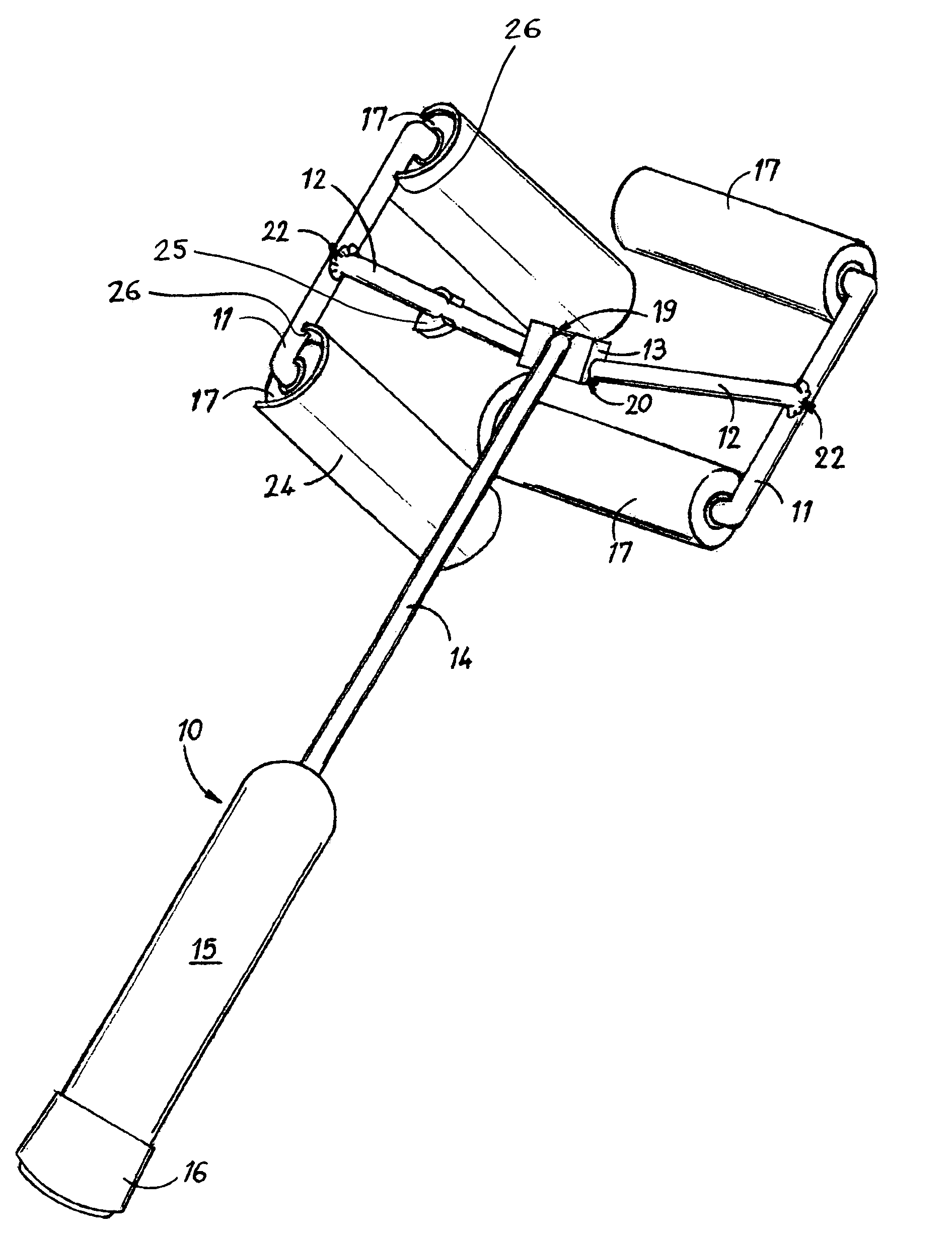
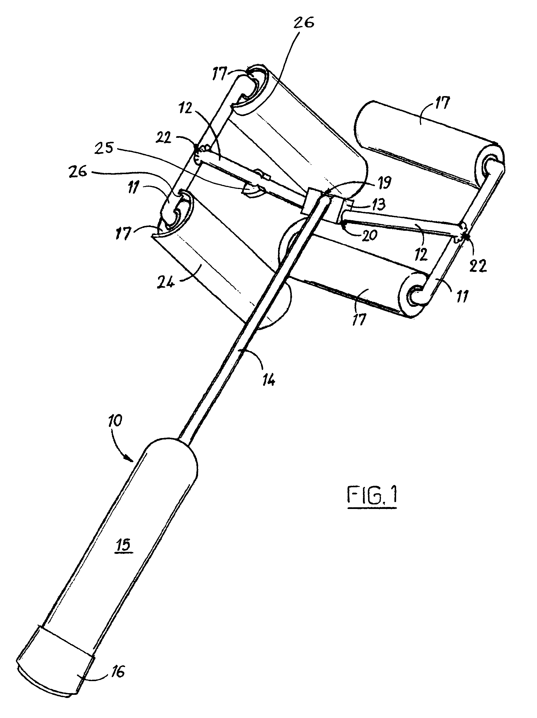
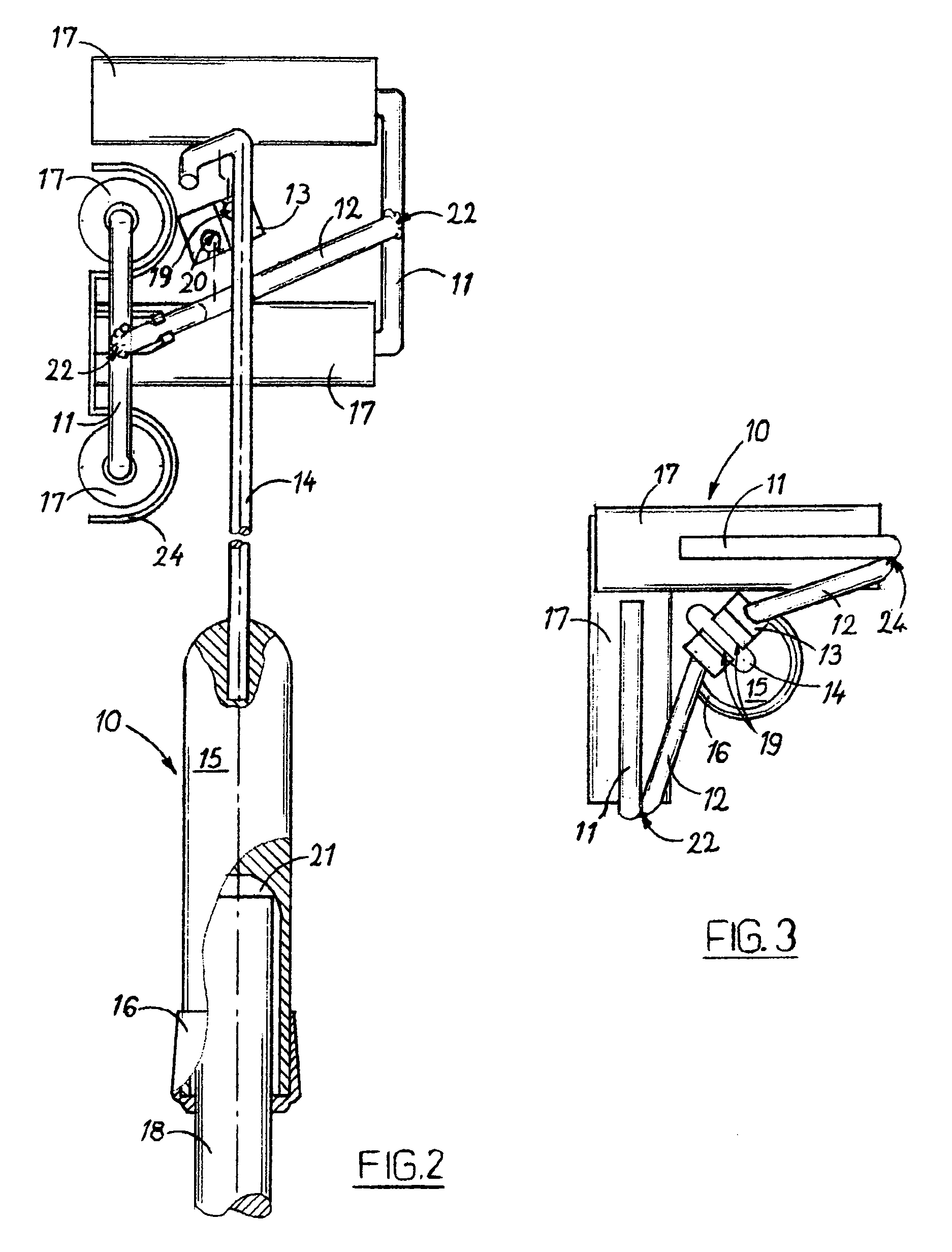
[0026]FIGS. 1–3 are, respectively, side, partially cross-sectioned / exploded, and end perspective views of a corner painting tool 10 according to a first embodiment of the present invention. The tool 10 generally comprises a plurality of rollers 17, at least two axle-bearing elements 11, a connector bar 12, a pivoting joint 13, a connector arm 14, and a handle 15.

[0027]As illustrated, the preferred embodiment employs two axle-bearing elements 11 each formed integrally to define a pair of parallel axles joined together by a crossbar 11, the crossbar 11 of each axle-bearing element being fixedly attached to the connector bar 12 such that the parallel axles of the two axle-bearing elements 11 are directed inward toward each other at substantially a right angle orientation. One skilled in the art will appreciate that additional axles (and rollers 17) may protrude from each crossbar 11, thereby allowing for additional sets of rollers on elements 11, effectively increasing the total number...


PUM


Abstract

Disclosed herein is a corner painting tool, typically comprising at least four replaceable rollers pivotally attached to a handle, that provides for the painting of the two adjoining surfaces forming a typical 90° interior corner in an even and efficient manner. Each pair of rollers is detachably attached to one of two axle-bearing elements that are, in turn, rigidly affixed at opposite ends of a connector bar. The fixed relationship between the connector bar and the axle-bearing elements serve to position each pair of rollers at a 90° angle to the other. A handle is pivotally attached at the midpoint of the connector bar. Attachment at the bar's midpoint serves to locate the pivot point as close as possible to the inside corner formed by the rollers, thereby maximizing the stability of the overall assembly during use. The pivoting connection provides a user with the flexibility of operation needed to reliably move the painting tool along an interior corner surface from virtually any location between the adjoining surfaces.

Description

BACKGROUND OF THE INVENTION[0001]1. Field of the Invention[0002]The present invention relates to painting tools and, more particularly, to a multiple-roller painting tool that provides for the painting of both walls adjoining an interior angle / corner evenly and simultaneously.[0003]2. Description of the Background[0004]Mainstream interior decorating relies heavily on painting, and a variety of different tools have evolved to help in accomplishing the same. One of the places where painting takes considerable time and effort is the typical internal angle / corner where two surfaces meet. Painting internal angles / corners is typically accomplished by manually applying paint with a brush using a constant and generous amount of paint with overlapping strokes in order to cover strips typically four inches wide along both adjoining surfaces. Moreover, tall walls increase the amount of time needed to paint because the use of a ladder is required in order to reach the top of the internal corner...

Claims


Application Information

Patent Timeline
Patent Type & Authority Patents(United States)
IPC IPC(8): B05C17/02
CPCB05C17/0227
Inventor RIVADENEIRA, HUGO P.
Owner RIVADENEIRA HUGO P
Why Eureka
Try Eureka