
Apparatus for dosage control

a technology of dosage control and apparatus, applied in the direction of process and machine control, positive displacement liquid engine, instruments, etc., can solve the problems of encumbering clothing selection, unobtrusive cumbersome and inconvenient installation,

Inactive Publication Date: 2005-10-25
ADVANCED NEUROMODULATION SYST INC
View PDF34 Cites 41 Cited by
  • Summary
  • Abstract
  • Description
  • Claims
  • Application Information

AI Technical Summary

Benefits of technology

[0014]A bellows may be attached to the housing in communication with the enclosure. The bellows may fill when the enclosure is in communication with an inlet port and drain when the enclosure is in communication with the outlet port. The bellows may also provide pressure or flow stability.

Problems solved by technology

These implantable systems are unobtrusive, unencumbering, and typically deliver smaller doses to targeted regions.
While external infusion pumps overcome some of the limitations of pills, injections, and suppositories, they are often cumbersome and inconvenient.
These devices must typically be worn or strapped to the patient, encumbering clothing selection and presenting a risk of damage to the external pump.
In addition, catheter incision points are subject to infection.
However, current versions of implantable infusion pump systems also have disadvantages.
Typically, implantable infusion pump systems provide limited programmability and patient control.
In addition, access to the pump system is limited.
In the case of variable rate pumps, prescriptions are limited by the available rate settings associated with the pump.
In pain management cases, this can lead to periods of under dosing and periods of unnecessary over treatment.
Doctors are also limited in the selection of prescriptions and often must have an office visit with patients to adjust prescriptions.
These adjustments are expensive to insurance companies, unprofitable for doctors, and inconvenient for patients.
Excess insulin can lead to shock and low insulin can lead to excess blood sugar levels and many long-term health problems.
Another problem with implantable infusion pumps is determining actual dosage rates and predicting reservoir levels.
Limited access to the pump means expensive preemptory refilling.
Typical implantable infusion pumps do not maintain rate data useful in determining actual dosage schedules and reservoir levels.
Therefore, doctors have difficulty predicting reservoir levels.
This often leads to wasted pharmaceutical solution.
Worse, the reservoir may empty and patents may suffer from a lack of treatment.
A further problem with current dose control systems lies in their method for controlling dose rates.
These methods often use many mechanical parts that may wear.
Further, these systems use parts that may malfunction under externally applied magnetic fields such as those of an MRI.
As such, typical infusion pumps suffer from deficiencies in providing prescription options, actual prescription rate data, and control of dosage.

Method used


Image

  • Apparatus for dosage control
  • Apparatus for dosage control
  • Apparatus for dosage control

Examples


embodiment 1

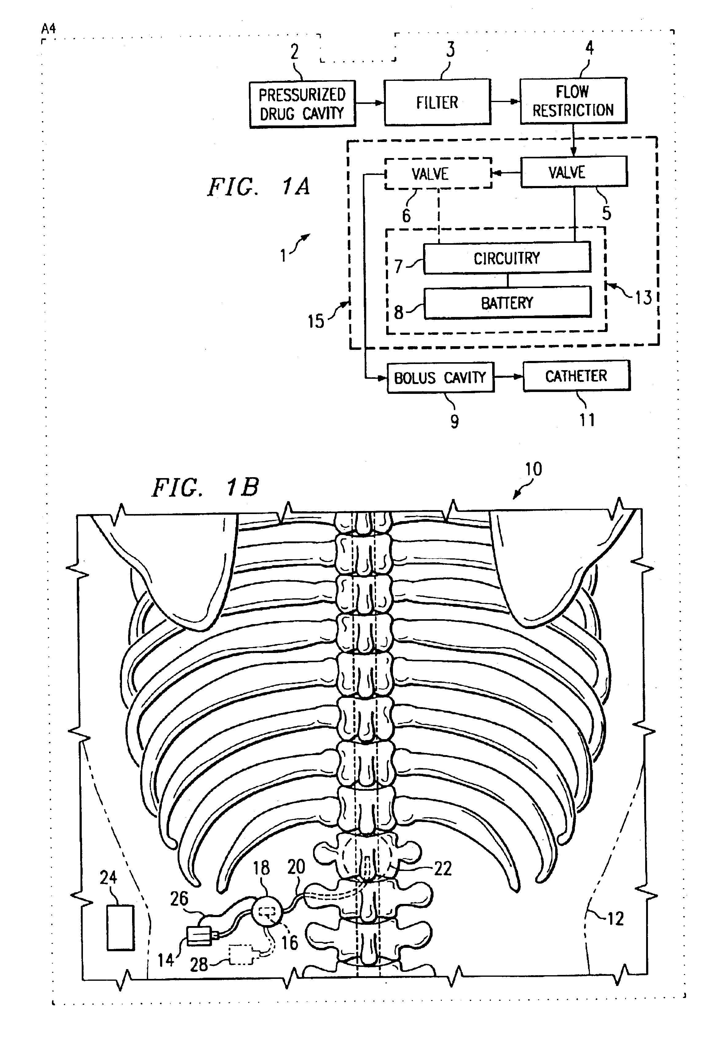
[0037]Such a delivery pattern is realized with a separate dose control system. FIG. 1A depicts an embodiment 1 of the present invention. A pressurized drug cavity 2 delivers a treatment solution through a filter 3 and flow restriction 4 to valves 5 and 6. However, various motivating systems may be envisaged for supplying valves 5 and 6 with treatment solutions. The circuitry 7 using energy from battery 8 manipulates the valves 5 and 6 to produce a flow rate in accordance with a prescription. However, one, two, or more valves may be used. The treatment solution may then travel through a catheter 11 to a treatment region in a patient. A bolus cavity 9 may be located inline to provide for the administering of bolus dosages.

[0038]The circuitry 7 and battery 8 comprise a dose control module and may be located separate from other elements as denoted by the enclosure 13. However, other elements such as the valves 5 and 6 may be included with the circuitry 7 and battery 8 as indicated by th...

embodiment 10

[0040]FIG. 1B shows another embodiment 10 of the present invention. FIG. 1B has an infusion pump 14 implanted in a patient 12. From the infusion pump, a catheter 20 leads through a dose control module 18 to a treatment area 22. The dose control module 18 may have a valve set 16 or other means of directing dosage. Alternately, the dose control module 18 may have a communication link 26 with the infusion pump 14 or valve set that aids in controlling dose. The system may also include an external patient control unit 24. The external patient control unit may direct the dose control module 18 to change dose rates or prescription configurations. In addition, other infusion pumps 28 may be connected with the dose control module 18 or valve set 16 such that multiple pharmaceutical solutions are delivered through the catheter 20 to the treatment area 22.

[0041]The system may be useful in treating various ailments. For example, the treatment area 22 may be intraspinal. The infusion pump 14 may...


PUM


Abstract

The invention is directed to a dose control apparatus for manipulating the dosage of one or more pharmaceutical solutions emanating from an implantable drug infusion pump. The dose control apparatus has a movable core that is held in a desired position by a magnet. The apparatus has at least one coil that, when activated, motivates the core to move to a new position. The core may be held in the second position by another magnet. The apparatus may have more that one coil provide various control options. In addition, the coils may be used to determine core position or the presence and strength of an externally applied magnetic field such as that produced in an MRI. The coils may also be used to produce a magnetic field counteracting the externally applied field or to produce a degaussing field.

Description

RELATED APPLICATIONS[0001]This application claims priority of U.S. patent aplication Ser. No. 60 / 412,365, filed Sep. 20, 2002 entitled: “Programmable Flow Controller”, and is incorporated herein by reference in its entirety.TECHNICAL FIELD OF THE INVENTION[0002]This invention, in general, relates to an implantable drug delivery system. More specifically, this invention relates to a dose control system and valves used to manipulate the delivery rate of a pharmaceutical solution.BACKGROUND OF THE INVENTION[0003]Implantable drug infusion therapy has been used to treat various ailments including pain management and diabetes. These drug pumps and delivery systems have been used to deliver pain medication, hormones such as insulin, and other pharmaceutical agents. For example, intraspinal drug delivery may be used to treat chronic pain. By utilizing these systems, pharmaceutical agents are delivered in relatively lower doses to a specific region of treatment. In this manner, full body dil...

Claims


Application Information

Patent Timeline
Patent Type & Authority Patents(United States)
IPC IPC(8): A61M5/168A61M5/142A61M39/22F04B49/22
CPCA61M5/14216A61M5/14276A61M5/16881F04B49/225A61M39/22A61M2005/14208A61M2205/3507Y10T137/88062Y10T137/8242Y10T137/86389Y10T137/0318
Inventor ERICKSON, JOHNDAGLOW, TERRY
Owner ADVANCED NEUROMODULATION SYST INC
Learn More