
Sensor for a belt retractor

Inactive Publication Date: 2005-10-25
TRW OCCUPANY RESTRAINT SYST
View PDF9 Cites 9 Cited by
  • Summary
  • Abstract
  • Description
  • Claims
  • Application Information

AI Technical Summary

Benefits of technology

[0004]According to the invention, a sensor is provided in which the predetermined angle of tilt for triggering the sensor can be maintained within narrow limits. Furthermore, a smaller noise development is to occur, which is caused in that in operation, on contact of the control lever and the control disc on the belt retractor, rattling noises could occur. This reduction of the rattling noises must not lead to the smooth running and the problem-free locking engagement of the control lever being impaired.
[0007]As has been found out in tests, through an interruption of the hitherto continuous support surface, a damping is achieved to reduce the noise formation and also a very precise triggering is achieved at the predetermined angle of tilt. Particularly when grooves are provided, a further effect also occurs. The dirt which is deposited in the course of time on the inertia body can be deposited in the pockets formed by the grooves. Also, the projecting support sections can lead to the dirt, which is deposited on the ball, being constantly stripped off.

Problems solved by technology

Furthermore, a smaller noise development is to occur, which is caused in that in operation, on contact of the control lever and the control disc on the belt retractor, rattling noises could occur.
Also, the projecting support sections can lead to the dirt, which is deposited on the ball, being constantly stripped off.

Method used


Image

  • Sensor for a belt retractor
  • Sensor for a belt retractor
  • Sensor for a belt retractor

Examples


Embodiment Construction

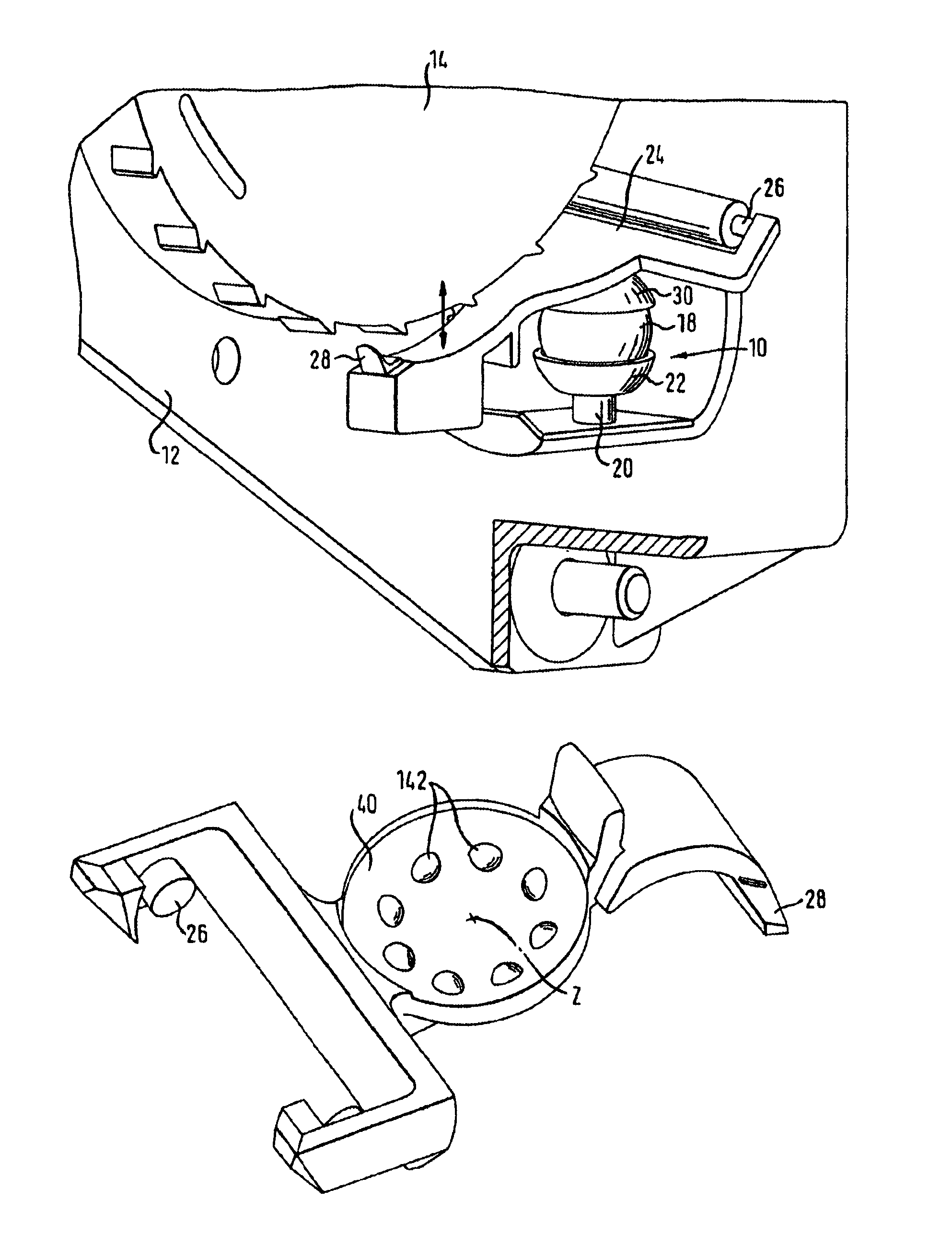
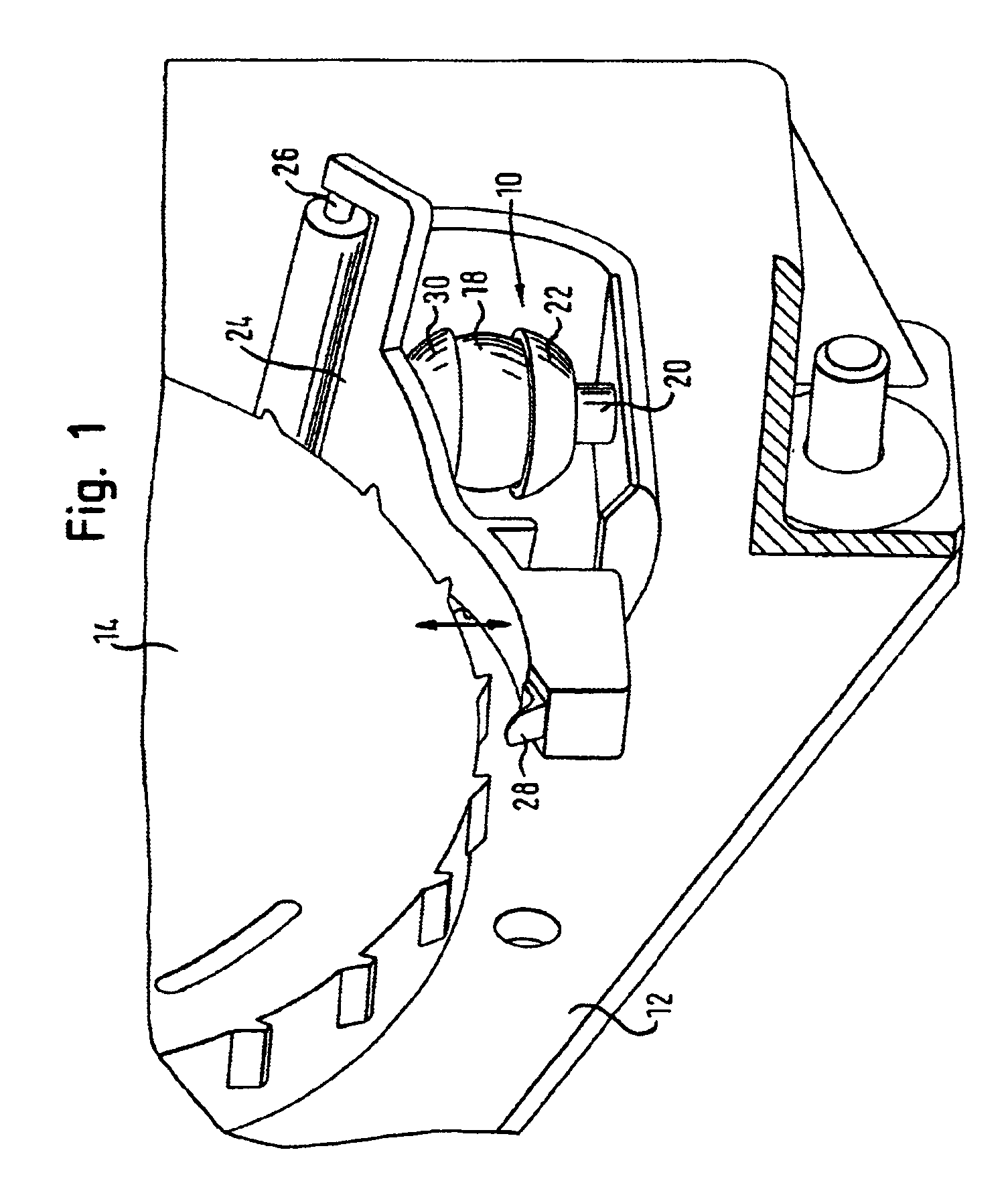
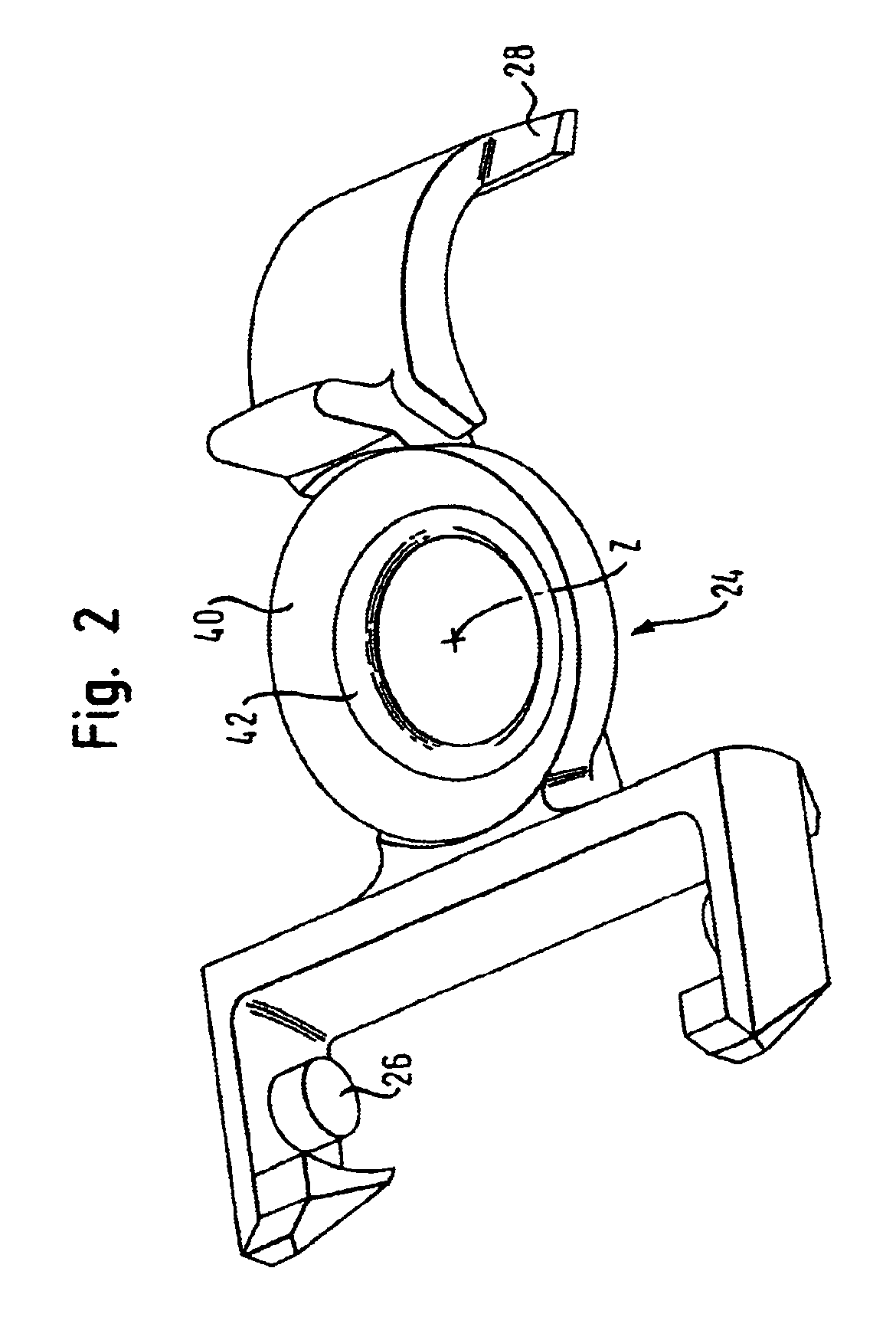
[0017]In FIG. 1 a sensor 10 is shown for the vehicle-sensitive triggering of the locking mechanism of a safety belt retractor. Reference 12 designates the housing of the safety belt retractor, in which the sensor 10 is housed. 14 in turn designates the diagrammatically illustrated control disc with its teeth. The sensor consists substantially of three parts, namely an inertia body in the form of a ball 18, a sensor lower part, also known as sensor housing 20, which has a lower shell 22 to hold the ball 18, and of a sensor lever 24. The sensor lever 24 is constructed as a one-armed lever, which is pivotally connected with the sensor housing 20 by means of a swivel bearing 26. At the opposite end, a control catch 28 is formed onto the sensor lever 20, which control catch 28 can engage into the teeth 16 when the sensor lever 24 swings upwards. In addition, an upper shell 30 is formed onto the sensor lever 20, which upper shell 30 rests on the ball 18 and into which the ball 18 projects...


PUM


Abstract

A sensor for triggering a vehicle occupant restraint system, in particular a locking mechanism of a belt retractor, comprises an inertia body, a lower shell in which the inertia body is received, and an upper shell which rests on the inertia body and into which it projects. The upper shell is part of a pivotally mounted sensor lever which swings on displacement of the inertia body and activates the locking mechanism. At least one of the shells has at least one projecting support section for abutment of the inertia body.

Description

TECHNICAL FIELD[0001]The invention relates to a sensor for triggering a vehicle occupant restraint system, in particular the locking mechanism of a belt retractor.BACKGROUND OF THE INVENTION[0002]Conventional sensors usually have an inertia body, a lower shell in which the inertia body is received, and an upper shell which lies on the inertia body and into which it projects, the upper shell being part of a pivotally mounted sensor lever which swings on displacement of the inertia body and activates the locking mechanism.[0003]Such a vehicle-sensitive sensor is known for example from the DE 298 22 610 and is installed into vehicle safety belt retractors. In the case of an impact of the vehicle, the inertia body, preferably a steel ball, moves and leads to the swinging of the sensor lever. A coupling catch on the sensor lever is thereby guided into the coupling teeth of a blocking mechanism, which finally blocks the belt spool and prevents a withdrawal of belt band. The triggering of ...

Claims


Application Information

Patent Timeline
IPC IPC(8): B60R22/34B60R22/40
CPCB60R22/40
Inventor KIELWEIN, THOMASRINK, JURGENSEMLER, BERND
Owner TRW OCCUPANY RESTRAINT SYST
Learn More