
Combination components for drives

A technology for combining components and driving devices, which is applied to transmission parts, electric components, transmissions, etc., and can solve problems such as disadvantages

Active Publication Date: 2017-09-26
STABILUS
View PDF1 Cites 0 Cited by
  • Summary
  • Abstract
  • Description
  • Claims
  • Application Information

AI Technical Summary

Problems solved by technology

This is troublesome and thus disadvantageous

Method used


Image

  • Combination components for drives
  • Combination components for drives
  • Combination components for drives

Examples


Embodiment Construction

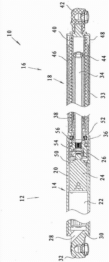
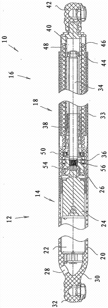
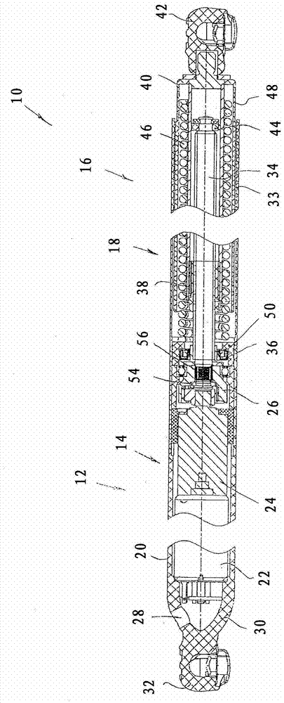
[0035] All three embodiments basically have the same basic structure, so the basic structure will be commonly described for all embodiments before introducing the differences of the three embodiments. Therefore, also the same reference numerals are used for the same parts in all three figures.

[0036] All three embodiments of the drive device 10 according to the invention comprise a rotary drive assembly 12 with a rotary drive 14 and a screw drive assembly 16 with a screw drive 18 .

[0037] The rotary drive 14 is accommodated in a housing tube 20 and comprises an electric motor 22 , downstream of which a reduction gear 24 is connected. On the transmission side, the reduction gear 24 is connected to a first clutch element 26 . Electrical connection lines (not shown) to the electric motor 22 can be introduced into the housing tube 20 through the opening 28 . Furthermore, a base part 30 is arranged at the free end of the housing tube 20 , which is provided with a ball seat 32...


PUM


Abstract

The device (10) has a threaded spindle (34) and a threaded nut (38) that are axially movable relative to one another in reaction to a rotation of a rotary drive (14). A rotary drive assembly (12) comprises the rotary drive and a coupling element (26), and a spindle drive assembly comprises a spindle drive (18) and another coupling element (36). The coupling element of the rotary drive assemblies and the coupling element of the spindle drive assembly are designed to be compatible with one another. A housing tube (20) and a base piece (30) are formed in one piece.

Description

technical field [0001] The invention contemplates a drive, in particular for a vehicle cover, comprising a rotary drive and a screw drive, the screw drive having a threaded screw and a nut arranged on the threaded screw, wherein the rotary drive is connected via a clutch unit to screw or nut connection, the clutch unit has a first clutch element on the side of the rotary drive and a second clutch element on the side of the screw drive, and wherein the screw and the nut are axially movable relative to each other in response to the rotation of the rotary drive . Background technique [0002] Such drives are generally known in the prior art. Reference is made by way of example only to DE 10 2008 008 743 A1. The design of the drive is usually selected to match the respective application. This results in a huge variety of different drive units, which must be kept in stock in order to be able to meet all customer requirements. The problem can be formulated in a simple manner a...

Claims


Application Information

Patent Timeline
Patent Type & Authority Patents(China)
IPC IPC(8): F16H25/20F16H57/028F16H57/029
CPCE05F15/622E05Y2800/205E05Y2800/242E05Y2800/402E05Y2800/72E05Y2900/50E05Y2900/546F16H25/20F16H25/2021F16H25/2454F16H57/029F16H57/031F16H57/033F16H2025/2031F16H2025/2075F16H2057/0335H02K7/06Y10T74/18624
Inventor L·安海尔U·普罗布斯特T·米勒M·布勒德
Owner STABILUS
Learn More