
Structure of an electrostatic precipitator

a precipitator and electrostatic technology, applied in the field of electrostatic precipitators, can solve the problems of inability to fit the spacing tubes in position, take a lot of time and labor to assemble the electrostatic precipitator, and the spacing tubes will be moved in the direction of the metal rods, etc., and achieve the effect of convenient fitting

Inactive Publication Date: 2005-10-25
HUNG HSING ELECTRIC CO LTD
View PDF33 Cites 14 Cited by
  • Summary
  • Abstract
  • Description
  • Claims
  • Application Information

AI Technical Summary

Benefits of technology

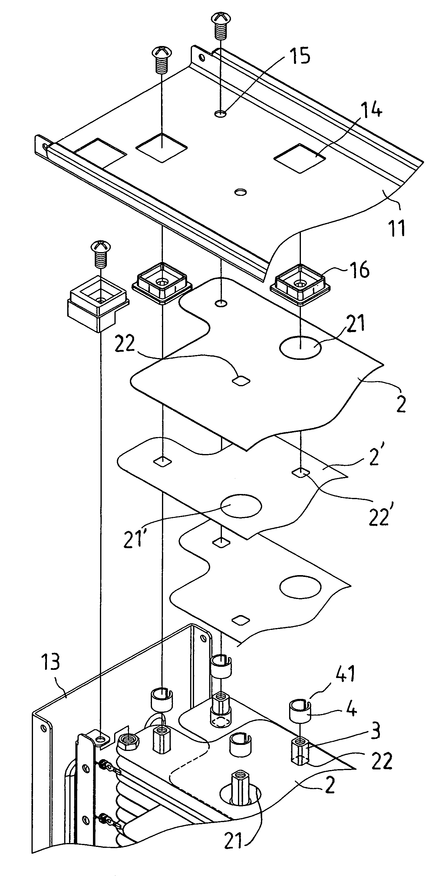
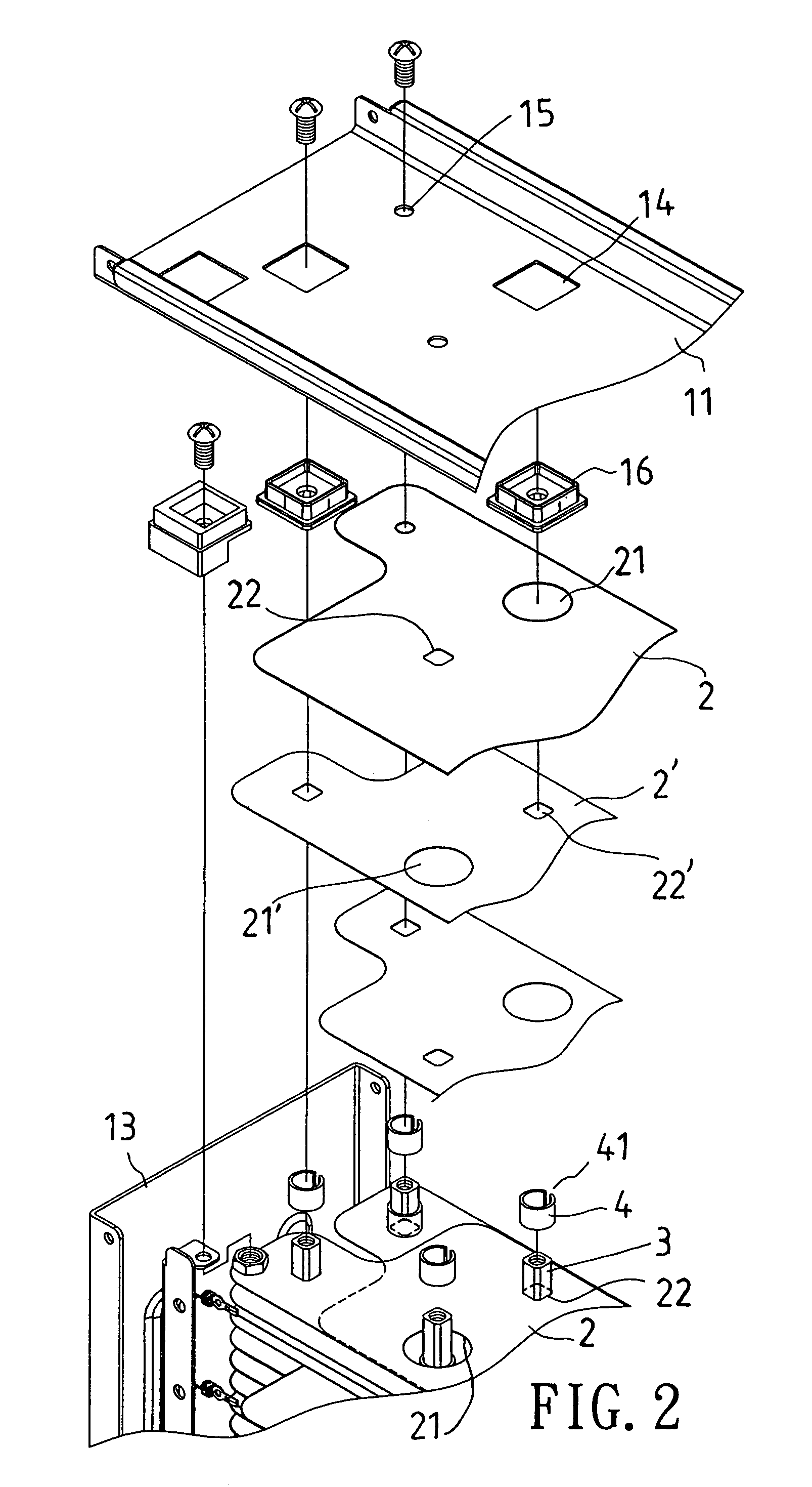
[0011]The electrostatic precipitator of the present invention includes a frame, several parallel square metallic rods securely disposed in the frame, and several metallic boards positioned parallel in the frame for charges to be deposited on, and spacing elements. The metallic boards have through holes thereon, and the metallic rods are passed through corresponding through holes of the metallic boards. The spacing elements are in the shape of a tube having a lengthwise extending gap, and they are positioned one on top of another around a whole length of the metallic rods for spacing the metallic boards equidistantly apart with. Furthermore, the spacing elements are flexible and resilient such that they can be easily fitted around the metallic rods, and such that they can tightly embrace the metallic rods.

Problems solved by technology

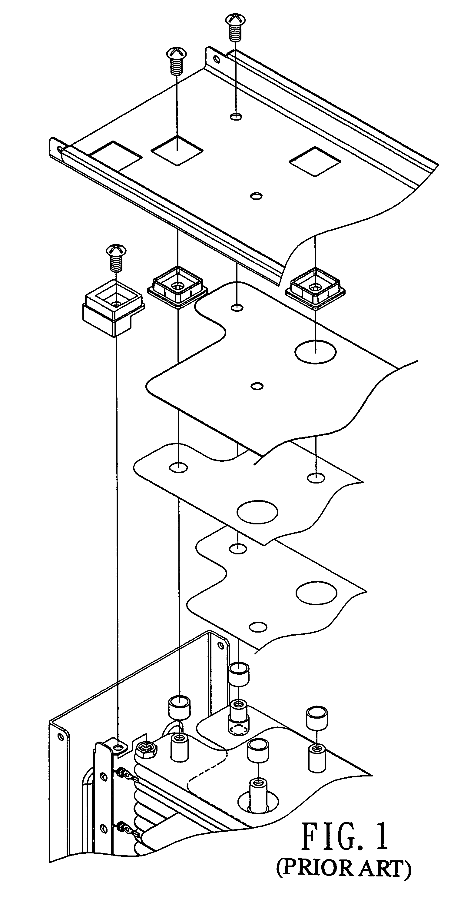
However, because all of the spacing tubes have to be passed around the metallic rods from the ends of the rods in assembling the electrostatic precipitator, it will be difficult to fit the spacing tubes in position, and in turns, it will take much time and labor to assemble the electrostatic precipitator if the inner diameter of the spacing tubes is close to the diameter of the metallic rods.
On the other hand, undesired displacement of the spacing tubes relative to the metallic rods will happen if the spacing tubes are formed with such a size as to be easily fitted around the metallic rods.

Method used


Image

  • Structure of an electrostatic precipitator
  • Structure of an electrostatic precipitator
  • Structure of an electrostatic precipitator

Examples


Embodiment Construction

[0019]Referring to FIGS. 2 and 3, a preferred embodiment of an electrostatic precipitator of the present invention includes a frame 1, a first group of metallic boards 2, a second group of metallic boards 2′, several metallic rods 3, and several spacing elements 4.

[0020]The frame 1 consists of an uppermost board 11, a lowermost board 12, and several supporting rods 13 whose upper and lower ends are respectively connected with edges of the uppermost board 11 and the lowermost board 12. Each of the boards 11 and 12 has several holding holes 14, and several fitting holes 15, each of which holding holes 14 has a plug 16 fitted therein.

[0021]The metallic rods 3 are square, and they are disposed upright in the frame 1 with upper ends thereof being connected with respective ones of the plugs 16 and the fitting holes 15 of the uppermost board 11, and with lower ends thereof being connected with respective ones of the plugs 16 and the fitting holes 15 of the lowermost board 12.

[0022]The spac...


PUM


Abstract

An electrostatic precipitator includes a frame, several parallel square metallic rods securely disposed in the frame, and several metallic boards positioned parallel in the frame for charges to be deposited on, and spacing elements; the metallic boards have through holes thereon, and the square metallic rods are passed through corresponding through holes of the metallic boards; the spacing elements are in the shape of a tube having a lengthwise extending gap, and they are positioned one on top of another around a whole length of the metallic rods for spacing the metallic boards equidistantly apart with; the spacing elements are flexible and resilient so as to tightly embrace the metallic rods when they are fitted around the rods.

Description

BACKGROUND OF THE INVENTION[0001]1. Field of the Invention[0002]The present invention relates to an electrostatic precipitator, more particularly one, including metallic boards for charges to be deposited on, metallic rods for supporting the boards in position, and spacing elements, which are positioned one on top of another around the rods for spacing the boards equidistantly apart, and which are formed with such a shape as to be easily fitted onto, and tightly embrace the metallic rods.[0003]2. Brief Description of the Prior Art[0004]Electrostatic precipitators, dust filtering devices, and ion generators are three major kinds of air cleaning devices, among which electrostatic precipitators occupy least space, can function with high dust collecting efficiency for longest period of time, and are convenient to use, and cheapest to manufacture and maintain.[0005]Referring to FIG. 1, a common structure of electrostatic precipitators includes a frame, several first and second metallic b...

Claims


Application Information

Patent Timeline
IPC IPC(8): B03C3/47B03C3/45B03C3/08B03C3/86
CPCB03C3/08B03C3/47B03C3/86
Inventor HUANG, PING
Owner HUNG HSING ELECTRIC CO LTD
Learn More