Structure of rotors in stepping motors

a technology of stepping motors and rotors, which is applied in the direction of magnetic circuit rotating parts, magnetic circuit shapes/forms/construction, instruments, etc., can solve the problems of making undesired vibration and/or noise, and achieve the effect of reducing vibration and noise, and accelerating the speed of rotation

Inactive Publication Date: 2005-10-25
WACHOVIA BANK NAT ASSOC AS AGENT +1
View PDF9 Cites 2 Cited by
  • Summary
  • Abstract
  • Description
  • Claims
  • Application Information

AI Technical Summary

Benefits of technology

[0010]Coping with above stated problems, the present invention is to provide a structure of a rotor in stepping motors capable of not only rotating much faster, but also eliminating undesired vibration and noises even under rotation at high speed.

Problems solved by technology

Meanwhile, one of the prior art, for example, (as disclosed in FIG. 4 of the above-mentioned Japanese Patent), wherein a permanent magnet is provided between two rotor components, is apt to make undesired vibration and / or noises because such a structure has magnetic salient portions (teeth) on the circumferential portion.

Method used


Image

  • Structure of rotors in stepping motors
  • Structure of rotors in stepping motors
  • Structure of rotors in stepping motors

Examples


first embodiment

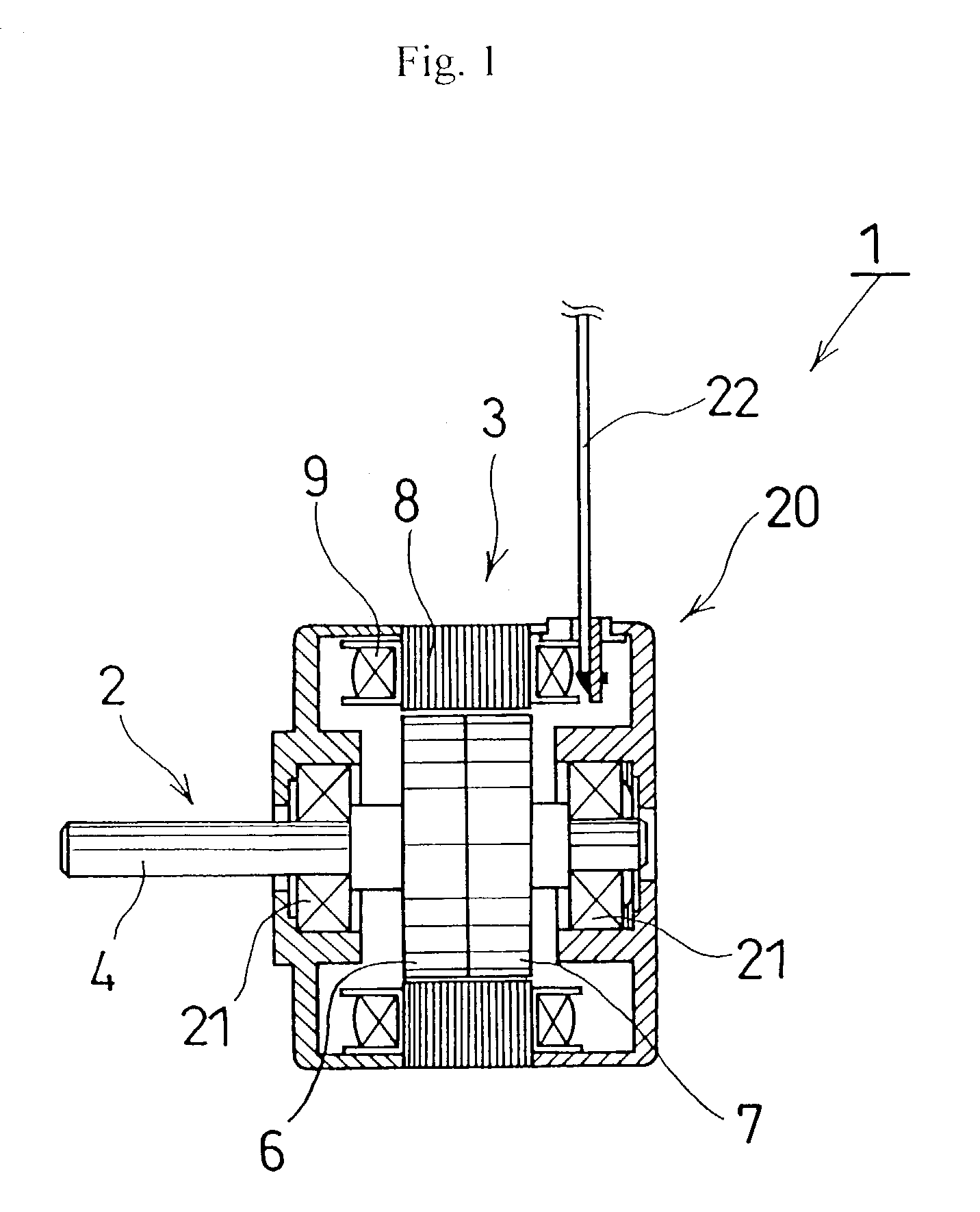
[0033]Referring to FIGS. 1 to 3, the present invention is described as follows.

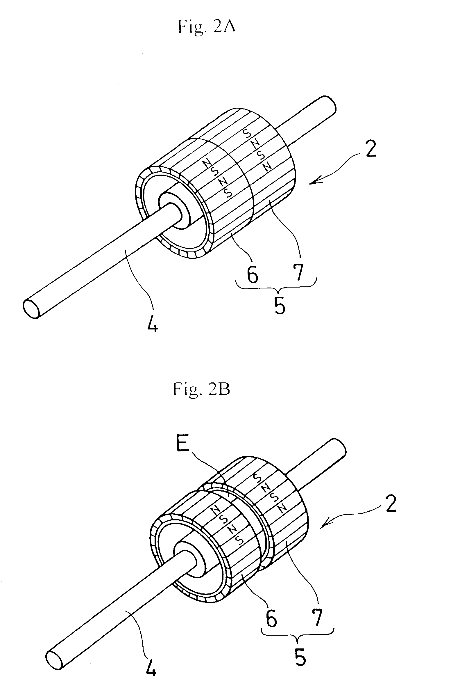
[0034]A stepping motor referred to as the first embodiment of the present invention has a stator 3 equipped in a housing 20, and enables a rotor 2 to rotate around a bearing 21 as shown in FIG. 1, and the rotor 2 comprises mainly a rotor axis 4 capable of rotating freely as being held by the bearing 21, and a magnetic component 5 that held by the rotor 4 by means of supporting portions (not shown) as shown in FIG. 2.

[0035]The magnetic component 5 comprises magnetic component portions 6 and 7 each shaped as an approximate ring. With regard to the magnetic component portions 6 and 7, it is possible that they are so fabricated that both of them are either combined firmly with each other in the axial direction as shown in FIG. 2A, or arranged separately at an appropriate vacant spacing inbetween in the axial direction as shown in FIG. 2B. For the convenience, hereinafter with regard to the magnetic component ...

second embodiment

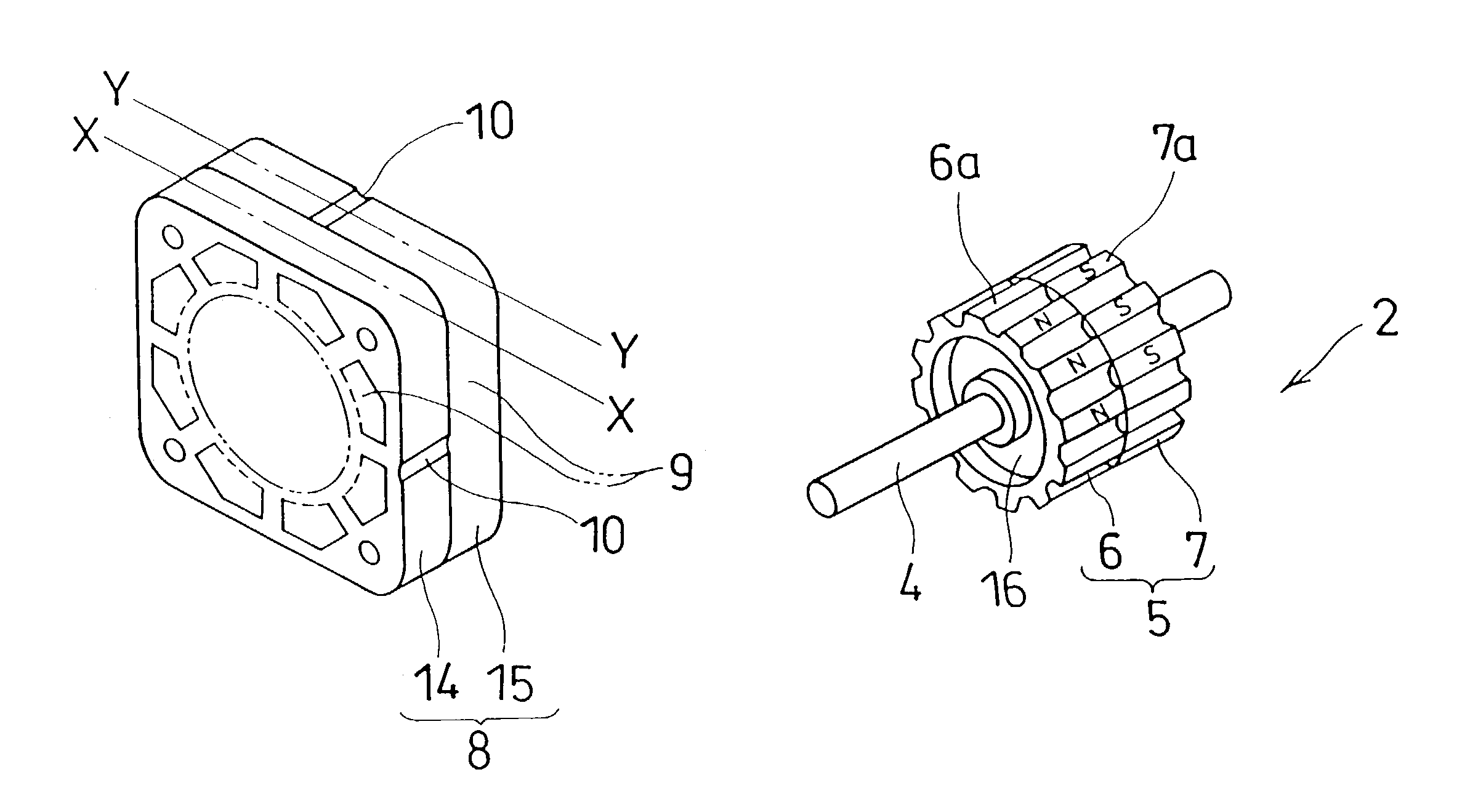
[0040]Furthermore, the stator 3 can be comprised of first and second stator yoke components 14 and 15 capable of being incorporated in, respectively (see FIG. 4 concerning the present invention described herein later), and the first and second stator yoke components are so arranged that the two yoke components are displaced with angle of either 90° or 180° with each other.

[0041]The coils 9 are provided correspondingly for the first and second magnetic component portions 6 and 7, and capable of producing magnetic force (both attractive and repulsive) between the coil 9 and the first magnetic component portion 6, and also between the coil 9 and the second magnetic component portion 7. The first and second magnetic component portions 6 and 7 are so arranged that contrary poles oppose each other in terms of their physical structure.

[0042]The magnetic component 5 of the rotor 2 described beforehand in the first embodiment takes a ring formation so that the distribution curve of the magne...

third embodiment

[0051]In the third embodiment, the first and second magnetic component portions 6 and 7 have convex portions 6a and 7a, having a lengthy rectangular physique, formed in the axial direction at appropriate spacing being like an approximate gear on the circumferential surface of each portion as shown in FIGS. 7A and 7B. The convex portion 6a of the first magnetic component portion 6 and the convex portion 7a of the magnetic component portion 7 are magnetized in the radial direction, so that contrary poles face each other when viewed in the axial direction. In this embodiment, for example, the convex portion 6a of the first magnetic component portion 6 is magnetized as N-pole, and the convex portion 7a of the magnetic component portion 7 as S-pole.

[0052]The first and second magnetic component portions 6 and 7 are combined or disposed at a predetermined spacing E in the axial direction, and the convex portions 6a and 7a are arranged so that a convex portion opposes a concave portion. In ...


PUM


Abstract

A stepping motor having a rotor that includes a magnetic component whose circumferential part is magnetized in multipole along the circumferential surface thereof, the stepping motor being capable of forcing the rotor to rotate by magnetic force provided between magnetic poles of the rotor and excited salient poles of a stator, in which the magnetic component includes two magnetic component portions each shaped as an approximate ring, and the two magnetic component portions are either combined with each other or set up separately at an appropriate spacing between them. The stepping motor is capable of rotating with not only high speed but also less undesired vibration and noises, and enabling a simpler, smaller manufacturing equipment thereof to be constructed.

Description

[0001]This is a Continuation of application Ser. No. 09 / 960,927 filed Sep. 25, 2001, now abandoned. The entire disclosure of the prior application is hereby incorporated by reference herein in its entirety.BACKGROUND OF THE INVENTION[0002]1. Field of the Invention[0003]The present invention relates to a structure of a rotor in a stepping motor, widely used for paper-feeders in facsimiles and scanners in copying machines.[0004]2. Description of the Related Art[0005]An example of prior art is a stepping motor having a rotor comprising a permanent magnet between two rotating components that are held by the rotor axis at an appropriate spacing, and one of the rotating component is magnetized as N-pole and the other as S-pole (see FIG. 4 in Japanese Patent Laid-open No. Hei 10-80124), or stepping motors having a rotor comprising a cylindrical permanent magnet with multi-polar magnetic parts arranged around the circumference thereof (see FIGS. 1 and 2 in the above-mentioned Japanese Paten...

Claims


Application Information

Patent Timeline
Patent Type & Authority Patents(United States)
IPC IPC(8): H02K37/14H02K37/12H02K37/18H02K1/27
CPCH02K37/18
Inventor KUROSAWA, SOICHIKANAZAWA, AKIOYOSHIDA, NAOHIRO
Owner WACHOVIA BANK NAT ASSOC AS AGENT
Why Eureka
Try Eureka