Siphonable check valve and method of making same

a check valve and siphon technology, applied in the field of filter tubes, can solve the problems of difficult to push the end of the siphon hose through the check valve to the bottom of the fuel tank, and achieve the effect of reducing the resistance to opening

Inactive Publication Date: 2005-11-01
EATON CORP
View PDF6 Cites 32 Cited by
  • Summary
  • Abstract
  • Description
  • Claims
  • Application Information

AI Technical Summary

Benefits of technology

[0005]The present invention provides a filler tube assembly for attachment to a vehicle fuel tank which employs a tubular body having an annular valve seat therein with a poppet valve therein which is biased to the closed position against the seating surface provided about the interior of the body. The tubular body has radially inwardly extending tapered ribs or vanes provided on the inlet end of the body upstream of the valve seating surface for diverting a siphoning hose laterally; and, the surface of the poppet is tapered to divert the end of the siphoning hose laterally through an aperture formed in the side of the filler tube body downstream of the valve seating surface. The poppet valve includes a resilient seal integrally formed thereon which provides for sealing against the valve seating surface with a minimum of bias force and thus minimum resistance to opening is encountered upon insertion of a refueling nozzle or siphoning hose therein.

Problems solved by technology

However, where a check valve has been employed in the filler tube downstream of the flapper valve to prevent overfill or liquid escape during vehicle rollover it has been found quite difficult to push the end of the siphon hose through the check valve to the bottom of the fuel tank once the hose has entered the tank.

Method used


Image

  • Siphonable check valve and method of making same
  • Siphonable check valve and method of making same
  • Siphonable check valve and method of making same

Examples


Embodiment Construction

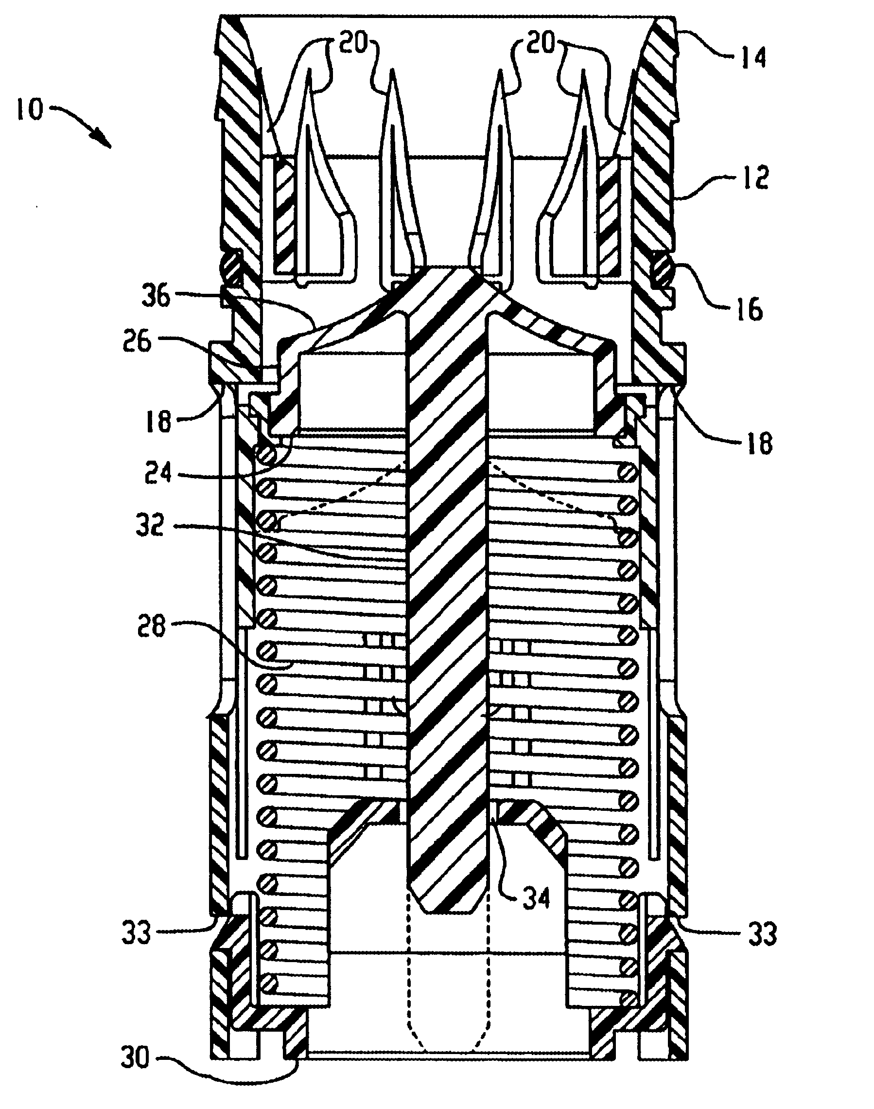
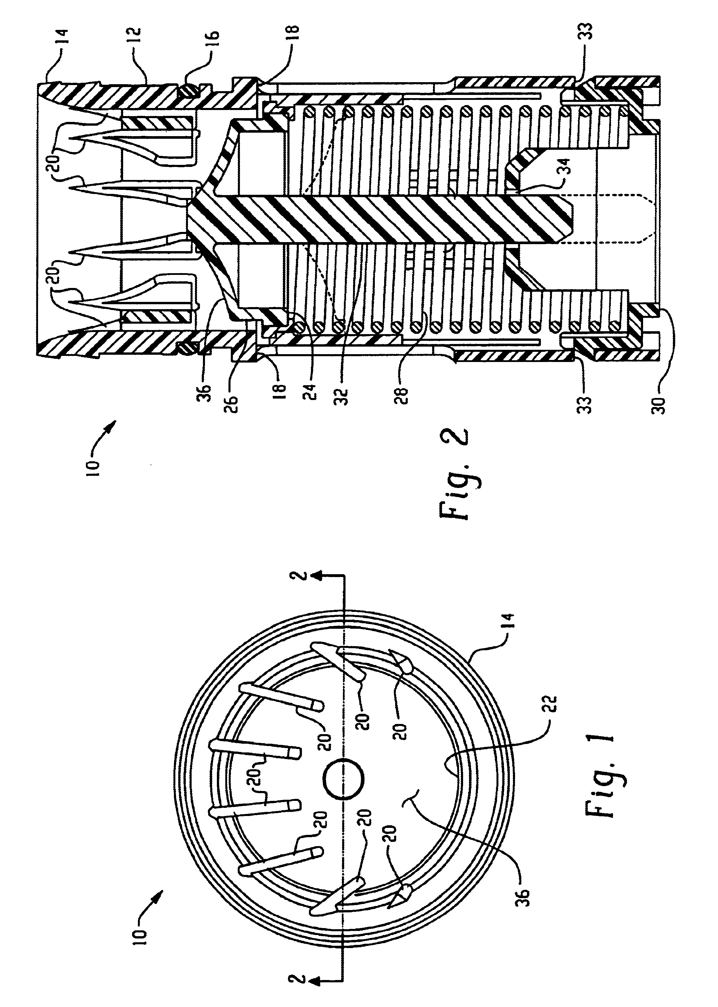
[0011]Referring to FIGS. 1 and 2, the valve assembly of the present invention is indicated generally at 10 and includes a tubular housing or body 12. The upper end of the body 12 has annular barbs 14 provided on the outer surface thereof for connection to the lower end of the tank filler tube (not shown). A sealing ring 16 is provided below the barbs 14 to provide a positive seal between the upper end of the body 12 and the filler tube.

[0012]The inner periphery of the body 12 adjacent the upper end has a plurality of circumferentially spaced radially inwardly extending ribs 20 preferably, by not necessarily formed integrally therewith, with each of the ribs having the inward edge thereof tapered in an axial direction as shown in FIG. 2. The radially inward edges of the ribs 20 define, in cooperation with portions 22 of the opposite side of the inner periphery of the body 12, a reduced cross-section opening which is offset from the center of the body. This offset opening is operative...


PUM

PropertyMeasurementUnit
resilient valvingaaaaaaaaaa
resilientaaaaaaaaaa
circumferenceaaaaaaaaaa

Abstract

A check valve for connection in a fuel tank filler tube. The valve has a tubular body with a plurality of radially inwardly extending vanes or ribs in the inlet end about a portion of the circumference. The ribs are tapered in the flow direction to deflect the end of a siphoning hose to an offset opening. A valve seat and poppet with a tapered surface are disposed downstream of the ribs, clearance apertures are formed in the side of the tubular body downstream of the valve seat. The tapered surface of the poppet, upon being opened by insertion of the end of a siphoning hose deflects the hose outwardly through the clearance apertures to facilitate further insertion into the tank. The poppet is biased normally closed by a spring.

Description

BACKGROUND OF THE INVENTION[0001]The present invention relates to filler tubes for motor vehicle fuel tanks and the problems related to controlling emission of fuel vapors therefrom during refueling operations.[0002]Currently, it is required to provide for controlling the emission to the atmosphere of fuel vapor during refueling when a nozzle has been inserted into the fuel tank filler tube for discharging fuel into the filler tube. Currently, vehicle fuel tank filler tubes are designed to have a baffle in the filler tube with a flapper valve having aperture sized to closely interfit the fuel discharge nozzle and thereby minimize the opening available for fuel vapor emission during refueling.[0003]However, it is now required to provide for withdrawal of fuel from the tank through the filler tube in the event that in service removal of the tank is required after the initial assembly of the vehicle. The withdrawal of fuel from the vehicle tank is usually accomplished by insertion of a...

Claims


Application Information

Patent Timeline
Patent Type & Authority Patents(United States)
IPC IPC(8): B60K15/04F02M37/00F16K15/16
CPCB60K15/04Y10T137/7925Y10T137/2911Y10T137/86332Y10T137/86372Y10T137/7932B60K15/035
Inventor KRISHNAMOORTHY, PK HARIDASSVERZYL, STEVEN A.BENJEY, ROBERT P.
Owner EATON CORP
Why Eureka
Try Eureka