Touch sensor with improved electrode pattern

a technology of electrode pattern and touch sensor, applied in the field of resistive and capacitive touch sensor technology, can solve the problems of increasing the chance of parasitic sourcing and sinking of current on the non-sourcing side, reducing the effective touch region, and reducing the effective touch area. the effect of equipotential line bunching

Active Publication Date: 2006-06-08
ELO TOUCH SOLUTIONS INC
View PDF11 Cites 24 Cited by
  • Summary
  • Abstract
  • Description
  • Claims
  • Application Information

AI Technical Summary

Benefits of technology

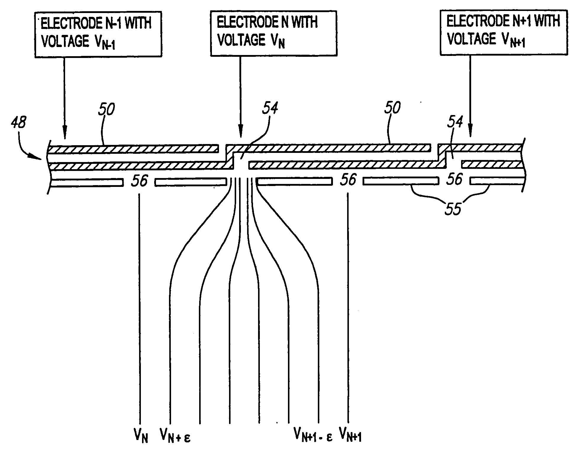
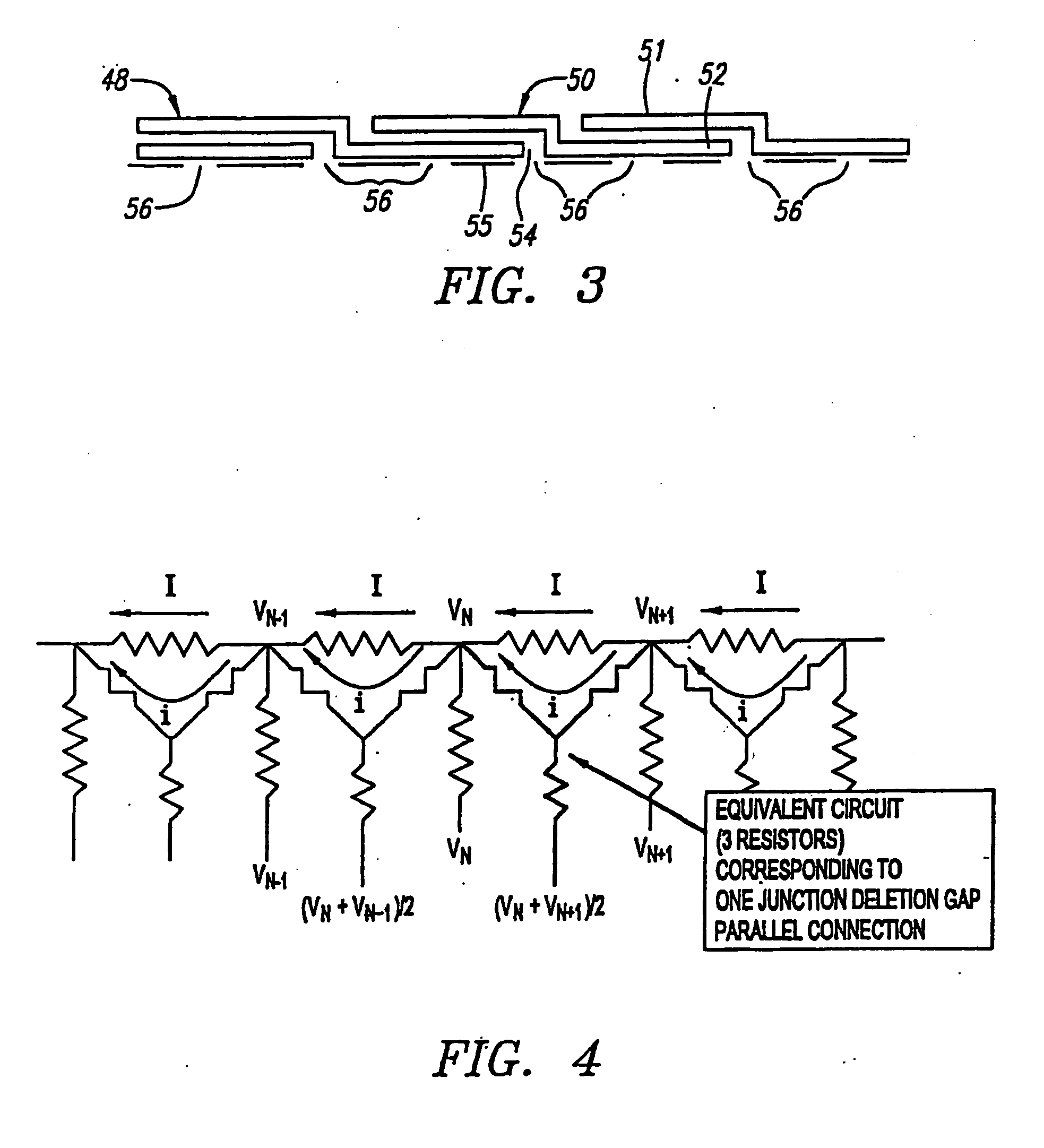
[0018] The touch sensor further comprises a conductive island located within the junction gap. In this manner, a voltage divider is formed within the junction gap, thereby minimizing bunching of equipotential lines on the electrodes during the non-sourcing mode. In the preferred embodiment, a conductive island is located within a plurality of the junction gaps to provide maximum benefit. To provide varying resistance between different gaps, e.g., a parabolic varying resistance along the length of the resistor chain, the non-junction gaps can be variously designed. For example, to provide maximum resistance, a non-junction gap may be empty, i.e., it contains no electrically conductive material. To provide minimum resistance, the non-junction gap may contain an extension from the inner portion of the electrode. To provide a resistance somewhere in between, the non-junction gap may contain a conductive island.

Problems solved by technology

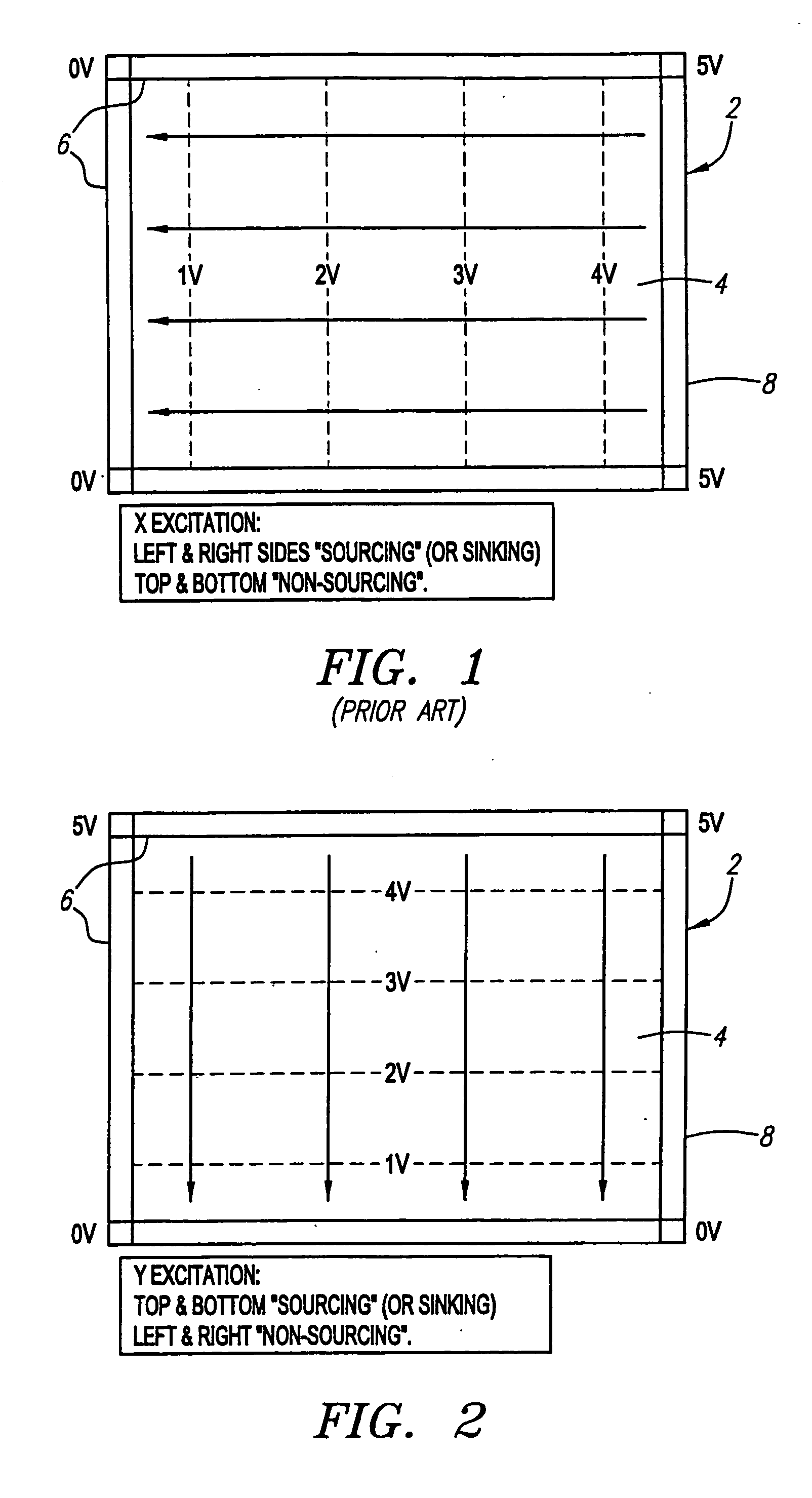
The current paths produce an undesirable ripple non-linearity in the touch region near the peripheral electrode pattern.
The considerable ripple adjacent to the top and bottom resistor chains limits the accuracy of measurements in this area, and thus, the size of the effective touch region is therefore reduced.
A problem arises in that while increasing the density of discrete electrical connections between the electrode border and the touch region improves linearity on the source sides, it provides more opportunities for parasitic sourcing and sinking of current on the non-sourcing sides.
A higher density of electrical connections on the non-sourcing side tends to make matters worse.
In particular, if there are more connections for the touch region than there are electrode voltages, then it is hard to avoid pairs of connections to the same electrode voltage and the consequent distortion of the desired linear voltage gradient.
While this may appear to be quite a reasonable engineering trade-off, the marketplace is wary of anything that degrades any aspect of touchscreen performance.

Method used


Image

  • Touch sensor with improved electrode pattern
  • Touch sensor with improved electrode pattern
  • Touch sensor with improved electrode pattern

Examples


Embodiment Construction

[0035] Referring to FIG. 7, a resistive touchscreen system 100 constructed in accordance with a preferred embodiment of the present invention is described. The touchscreen system 100 generally comprises a touchscreen 105 (i.e., a touch sensor having a transparent substrate), controller electronics 110, and a display 120. The touchscreen system 100 is typically coupled to a host computer 115. Generally, the controller electronics 110 receives from the touchscreen 105 analog signals carrying touch information. The controller electronics 110 also sends to the touchscreen 105 excitation signals. Specifically, the controller electronics 110 establishes a voltage gradient across the touchscreen 105. The voltages at the point of contact are representative of the position touched. The controller electronics 110 digitizes these voltages and transmits these digitized signals, or touch information in digital form based on these digitized signals, to the host computer 115 for processing.

[0036]...


PUM


Abstract

A touch sensor includes a substrate with a touch region, and a series resistor chain for creating electrical fields across the touch region. The resistor chain comprises a plurality of conductive electrodes that to form overlap resistors therebetween. The electrodes have inner portions that are separated by junctions. The touch sensor also includes insulating regions between the touch region and the resistor chain. The insulating regions are separated by gaps to provide a plurality of conductive pathways to the touch region, thereby minimizing non-linear ripple along the sourcing sides of the substrate. Some of the gaps are junction gaps that are formed between the touch region and junctions. Electrically conductive islands are placed within the junction gaps to provide an electrical node within each junction gap, thereby preventing bunching of equipotential lines within the junction, and minimizing non-linear ripple along the non-sourcing sides of the substrate.

Description

RELATED APPLICATIONS [0001] This application claims the benefit of the filing date of U.S. Provisional Patent Application Ser. No. 60 / 373,022, filed Apr. 16, 2002, and entitled “Touchscreen Having A Series Resistor Chain On The Periphery Of A Touch Area,” which is expressly incorporated herein by reference.FIELD OF THE INVENTION [0002] The field of the present invention relates to touch sensor technology, and more particularly to resistive and capacitive touch sensor technology. BACKGROUND OF THE INVENTION [0003] Touch sensors are transparent or opaque input devices for computers and other electronic systems. As the name suggests, touch sensors are activated by touch, either from a user's finger, or a stylus or some other device. Transparent touch sensors, and specifically touchscreens, are generally placed over display devices, such as cathode ray tube (CRT) monitors and liquid crystal displays, to create touch display systems. These systems are increasingly used in commercial appl...

Claims


Application Information

Patent Timeline
Patent Type & Authority Applications(United States)
IPC IPC(8): G09G5/00G06F3/041G06F3/045
CPCG06F3/045G06F2203/04113
Inventor AROYAN, JAMES L.SCHARFF, DANIEL H.
Owner ELO TOUCH SOLUTIONS INC
Why Eureka
Try Eureka