Inflatable body with independent chambers and methods for making the same

a technology of independent chambers and inflatable bodies, applied in the field of inflatable bodies with independent chambers and methods for making the same, can solve the problems of sharp transition zones, achieve the effects of low melting point, low melting point, and effective joining

Active Publication Date: 2009-01-27
CASCADE DESIGNS INC
View PDF5 Cites 10 Cited by
  • Summary
  • Abstract
  • Description
  • Claims
  • Application Information

AI Technical Summary

Benefits of technology

[0007]By extending the intermediate panel into the perimeter portion of both major panels, it is possible to effectively join the two major panels without modification to construction techniques for standard non-chambered bodies: the use of an intermediate panel with joining properties similar to those of the major panels ensures that, when the major panels are joined at their respective perimeters, the subsequent connection transcends the intermediate panel. Further, if care is taken to minimize bunching at the intermediate panel perimeter, the aesthetic qualities of the resulting product are similar to conventional, non-chambered inflatable bodies. Furthermore, because only the perimeter portions of the intermediate panel are subject to joining with the major panels, the techniques used to achieve this association need only be present or applied to those portions of the intermediate panel, e.g., the low melting point urethane coating need only be established at the perimeter of the intermediate panel.

Problems solved by technology

However, if unique zones of IFD values are desired, the modifications must be made to the auxiliary structure, which will either minimize the benefits of the self-inflating pad portion or result in sharp transition zones if the structure is not homogeneous.

Method used


Image

  • Inflatable body with independent chambers and methods for making the same
  • Inflatable body with independent chambers and methods for making the same
  • Inflatable body with independent chambers and methods for making the same

Examples


Embodiment Construction

[0018]The following discussion is presented to enable a person skilled in the art to make and use the invention. Various modifications to the preferred embodiment will be readily apparent to those skilled in the art, and the generic principles herein may be applied to other embodiments and applications, without departing from the spirit and scope of the present invention as defined by the appended claims. Thus, the present invention is not intended to be limited to the embodiment shown, but is to be accorded the widest scope consistent with the principles and features disclosed herein.

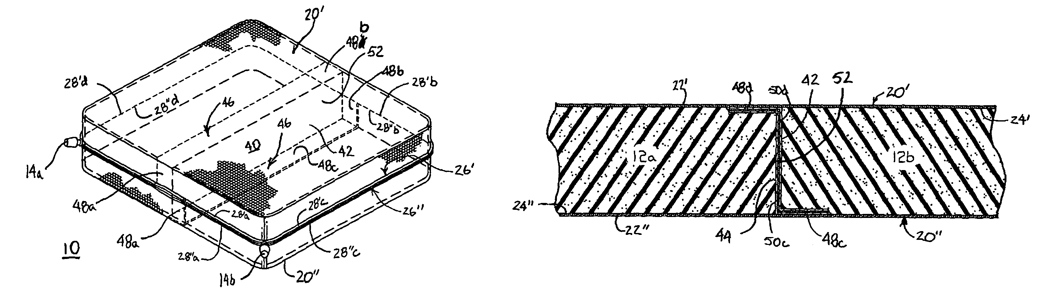
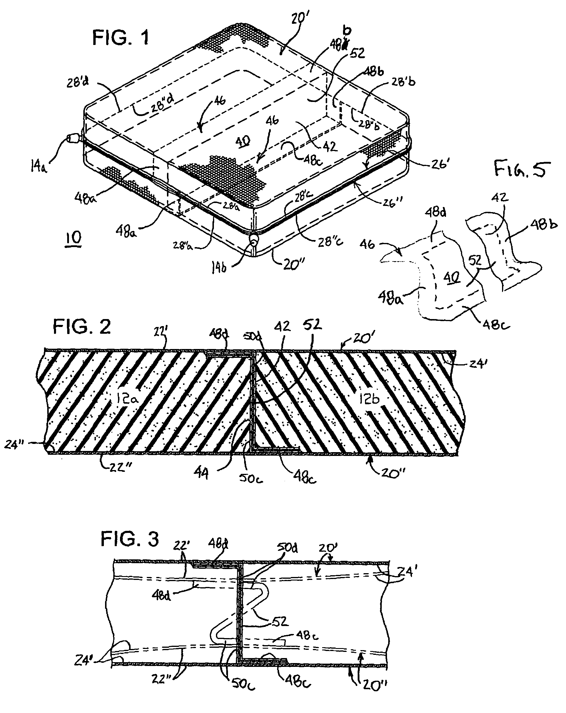
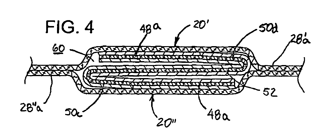
[0019]Turning then to the several Figures wherein like numerals indicate like parts, and more particularly to FIGS. 1 and 2, a first embodiment of the invention is shown. Self-inflating seat cushion 10 comprises upper major panel 20′, lower major panel 20″, open cell foam elements 12a and 12b, which are separated from each other by intermediate panel 40, and valves 14a and 14b. Upper and lower major pa...


PUM


Abstract

An inflatable body including first and second fluid impervious major panels, each having an outer surface, an inner surface and a perimeter, and further including a fluid impervious intermediate panel having a first surface, a second surface and a perimeter. A first perimeter portion of the intermediate panel is joined to the inner surface of the first major panel from one perimeter portion thereof to a generally opposed perimeter portion thereof, and a second perimeter portion of the intermediate panel, which is generally opposed to the first perimeter portion, is joined to the inner surface of the second major panel from one perimeter portion thereof to a generally opposed perimeter portion thereof. The first and second major panel perimeters are joined to each other, defining a primary enclosure having first and second chambers separated by the intermediate panel, and at least one sealable orifice in fluid communication with the environment and at least one chamber.

Description

BACKGROUND OF THE INVENTION[0001]Inflatable bodies such as mattresses and cushions are used for a variety of purposes. In certain applications, especially in the medical fields, it is particularly desirable to modify the resiliency or Indentation Force Deflection (“IFD”) value of a mattress or a cushion over a given area. For example, and with respect to seating cushions, various portions of a user's anatomy require different levels of support. This recognition lead to the development of the invention disclosed in U.S. Pat. No. 5,282,286, which is incorporated herein by reference. Here, discrete resilient slabs of material are placed adjacent to one another within a single envelope or enclosure to provide different zones of IFD values. While achieving the objective of providing differentiated zones of IFD values within a single self-inflating seat cushion, the invention did not provide for modulating the cushion's internal air pressure for each or several zones.[0002]Other attempts ...

Claims


Application Information

Patent Timeline
Patent Type & Authority Patents(United States)
IPC IPC(8): A47C27/10A47C27/14
CPCA47C27/081A47C27/087A47C27/088A47C27/10
Inventor NICKERSON, L. PAULHITCH, PHILIP R.
Owner CASCADE DESIGNS INC
Why Eureka
Try Eureka