Connectors for concrete footer frames

a technology of connecting rods and concrete, applied in the field of laying up forms, can solve the problems of weak joints, inconvenient use, and often damaged forms, and achieve the effect of convenient use and inexpensive production

Inactive Publication Date: 2006-07-27
ALBANO ROCCHINO
View PDF9 Cites 2 Cited by
  • Summary
  • Abstract
  • Description
  • Claims
  • Application Information

AI Technical Summary

Benefits of technology

[0006] The connector of the present invention consists of a stamped, sheet metal bracket which sits over the top edge of the form boards spanning the joint therebetween. The bracket can extend downwardly over the inside face and outside face of the form boards, and is secured in place with a number of double headed nails. The connector of the present invention is simple and easy to use, is inexpensive to produce, and is effective in joining form boards in rigid relationship. Also, the present form connector does not cause damage to the form boards when in use or when being removed, and can be used over again. Further, the present connector can be used with dimensional lumber form boards. No specially made form boards are needed for use with this connector.

Problems solved by technology

While this method can result in a satisfactory joint, it is an inefficient method in that wood must be cut to length and applied over the joint with sufficient nails to secure the splice.
When such a splice is removed, as the forms are taken up, the forms are often damaged and cannot be reused.
Nailing into an end grain of a form board results in a weak joint.
Again, the form boards are often destroyed when the forms are removed from the cured concrete.
Most of these devices are complex in structure, complicated to use, and expensive to manufacture.
A drawback of this connector is that the form boards must be preconfigured with the studs that the connector must engage.
This limits its use to forms specifically made for this connector.

Method used


Image

  • Connectors for concrete footer frames
  • Connectors for concrete footer frames
  • Connectors for concrete footer frames

Examples


Embodiment Construction

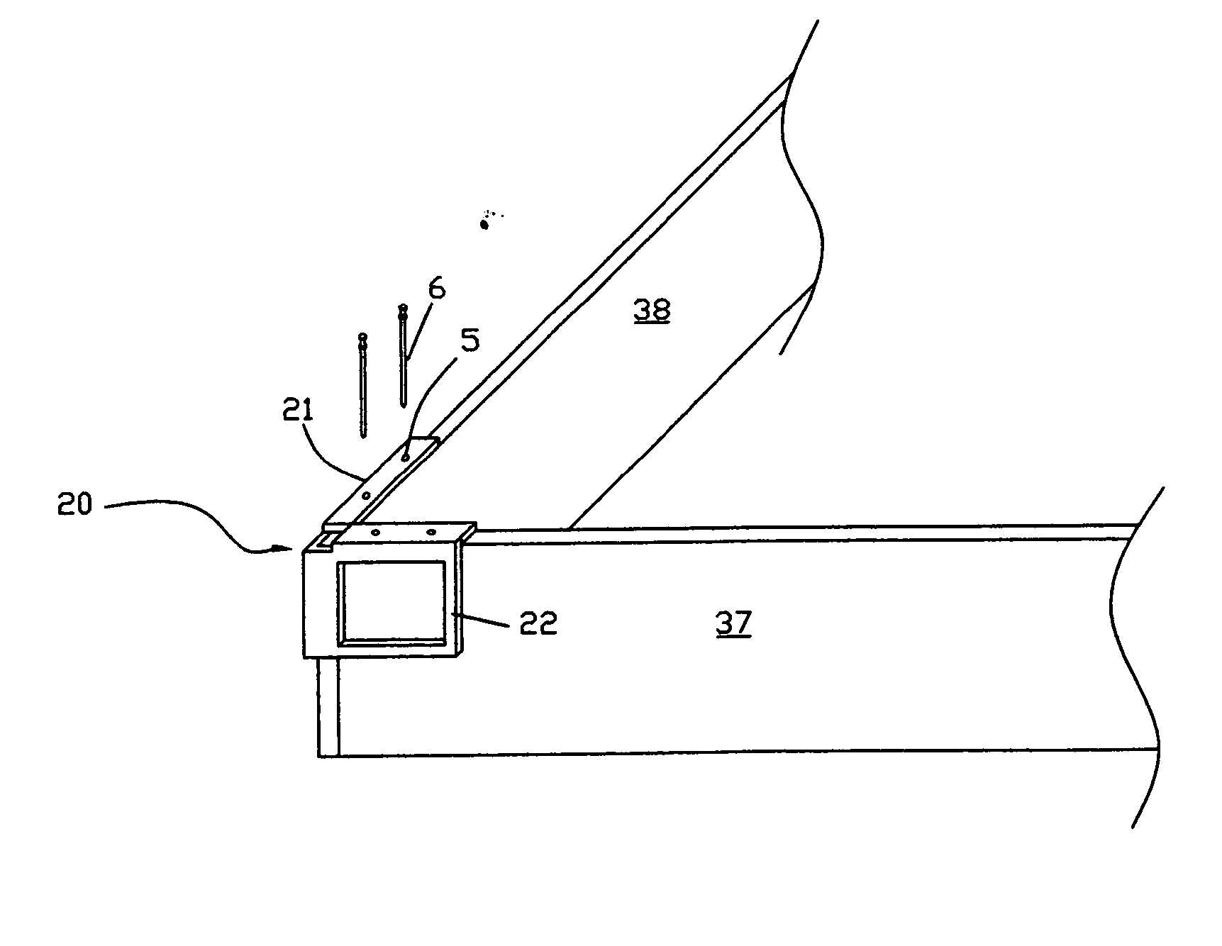
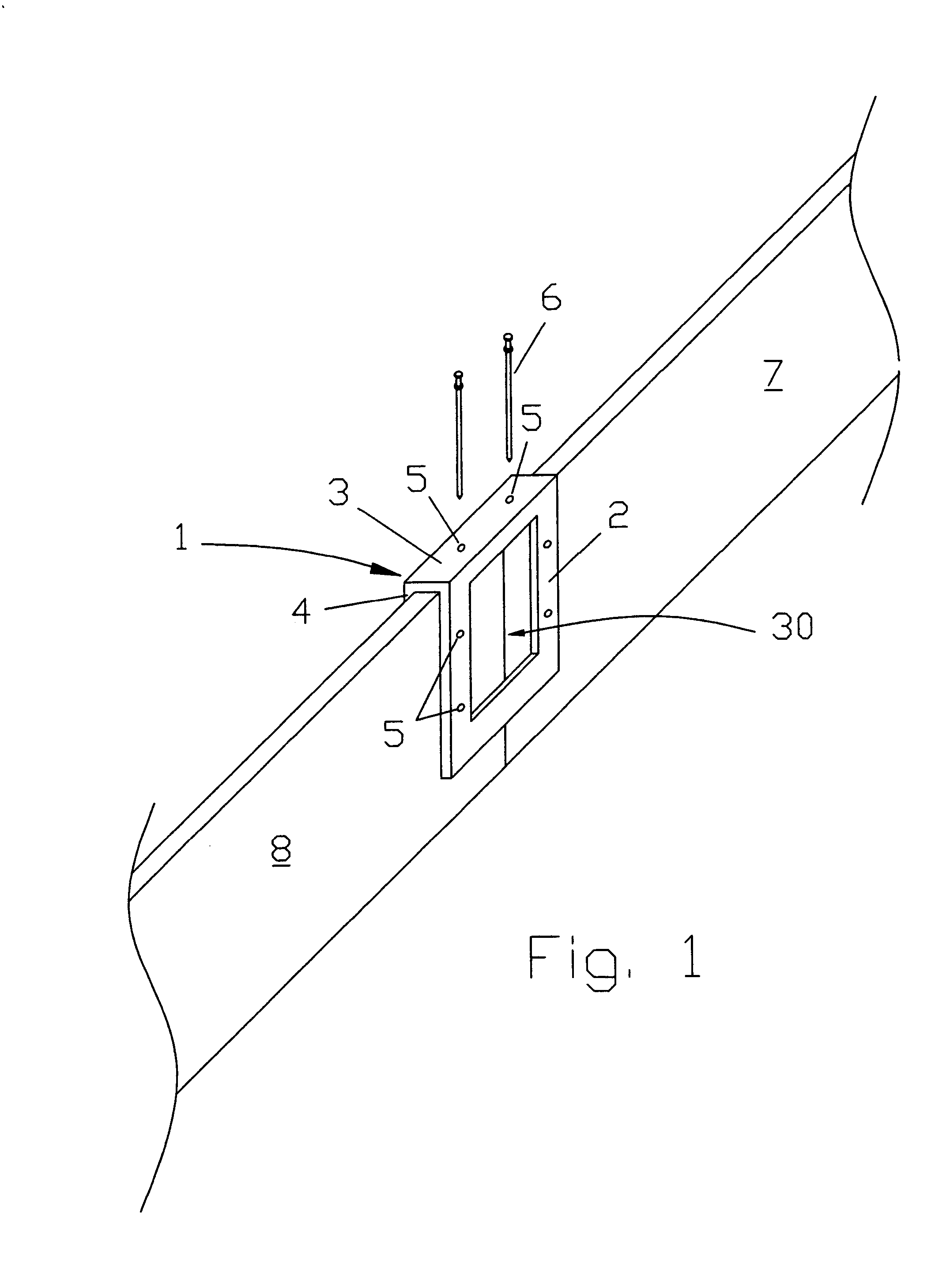
[0014]FIG. 1 shows a first embodiment of the form connector 1 in use connecting two form boards 7 and 8 in an end-to-end abutting relationship. Form connector 1 consists of a sheet metal body having an outside portion 2, a top portion 3, and an inside portion 4. Form connector 1 sits atop the joint between two form boards 7 and 8, spanning the joint therebetween. Outside portion 2 extends downwardly from the top of the form boards and extends over a portion of the outsides of the form boards. Top portion 3 is connected to the outside portion 2 and extends across the upper surface of the form boards, also spanning the joint therebetween. Connected to the top portion 3 is an inside portion 4, which extends downwardly from top portion 3 and extends over a part of the inside surface of the form boards 7 and 8. Nail holes 5 are strategically placed on the outer portion 2 and top portion 3 allowing for double headed nails 6 to pass therethrough, securing the connector 1 to the form boards...


PUM


Abstract

A stamped, sheet metal, form connector connects two concrete form boards together in end-to-end abutting relationship in one embodiment. In another embodiment, the connector connects two form boards in overlapping relationship. In a third and fourth embodiment, the connector connects two form boards at an inside and outside corner, respectively. Double headed nails fasten the connector to the form boards, allowing for easy removal without damage to the forms. The connector is inexpensive to manufacture, and is simple and convenient to use.

Description

BACKGROUND OF THE INVENTION [0001] The present invention relates to the masonry field, especially to the art of laying up forms in which concrete footings are poured. Forms for concrete footings are usually made of dimensional lumber or heavy plywood panels, or may even be manufactured aluminum panels. Where these lengths of lumber or panels are laid up end to end, they must be joined together in a fixed relationship, so that the concrete will not blow out the joint in the forms. [0002] A typical method of joining form boards in end to end relationship is to nail a splice board over the joint. While this method can result in a satisfactory joint, it is an inefficient method in that wood must be cut to length and applied over the joint with sufficient nails to secure the splice. When such a splice is removed, as the forms are taken up, the forms are often damaged and cannot be reused. [0003] Another method of joining forms at corner joints is to nail through the face of one form boar...

Claims


Application Information

Patent Timeline
Patent Type & Authority Applications(United States)
IPC IPC(8): E04B1/00E02D1/00
CPCE04B2001/2644E04B2001/2692E04G13/00E04G17/001E04G17/02
Inventor ALBANO, ROCCHINO
Owner ALBANO ROCCHINO
Why Eureka
Try Eureka