Joint fitting between members and joint structure and joining method of upper and lower floor vertical frame members

a vertical frame and joint fitting technology, applied in couplings, building repairs, instruments, etc., can solve the problems of complex installation, high cost, and high installation ability, and achieve the effect of simple structure joint fitting, easy joining and easy engagemen

Inactive Publication Date: 2010-12-28
NIPPON STEEL CORP
View PDF21 Cites 3 Cited by
  • Summary
  • Abstract
  • Description
  • Claims
  • Application Information

AI Technical Summary

Benefits of technology

[0006]Further, a simple structure joint fitting able to transmit the stress of both compressive force and tensile force no matter what direction, that is, the vertical direction or horizontal direction or an inclined direction, arranged in has been desired.
[0045]According to the 17th aspect of the invention, at least one of the female thread fittings to be arranged at the upper floor side is attached to the bolt in the joint fitting between members and the bolt is arranged from the upper floor side to the lower floor side in the state with the female thread fitting being used to prevent the bolt from dropping to the lower floor side, so the bolt can be arranged bridging the upper and lower floors in the state not dropping to the lower floor side, therefore the work of placement of the bolt becomes easy and the subsequent attachment of the female thread fittings and other parts to the bolt, in particular, the attachment of the joint hardware from the horizontal direction, also can be easily performed so the work of joining the upper and lower floor vertical frame members can also be easily performed, the upper and lower floor vertical frame members can be efficiently joined using the joint fitting of the present invention, and the installation cost can be reduced.

Problems solved by technology

Therefore, the horizontal direction distance L from the joint part between the hold down hardware 30 and 31 and the vertical frame members to the center axis C of the connection bolt becomes larger, hold down hardware 30 and 31 with large bending rigidity are required, and the installation is complicated and at high cost.
Further, there is the problem that insertion of the flanged cylindrical body 27 into the floor assembly 32 requires a high level of installation ability.

Method used


Image

  • Joint fitting between members and joint structure and joining method of upper and lower floor vertical frame members
  • Joint fitting between members and joint structure and joining method of upper and lower floor vertical frame members
  • Joint fitting between members and joint structure and joining method of upper and lower floor vertical frame members

Examples


Embodiment Construction

[0082]Next, the present invention will be explained in detail based on the illustrated embodiments.

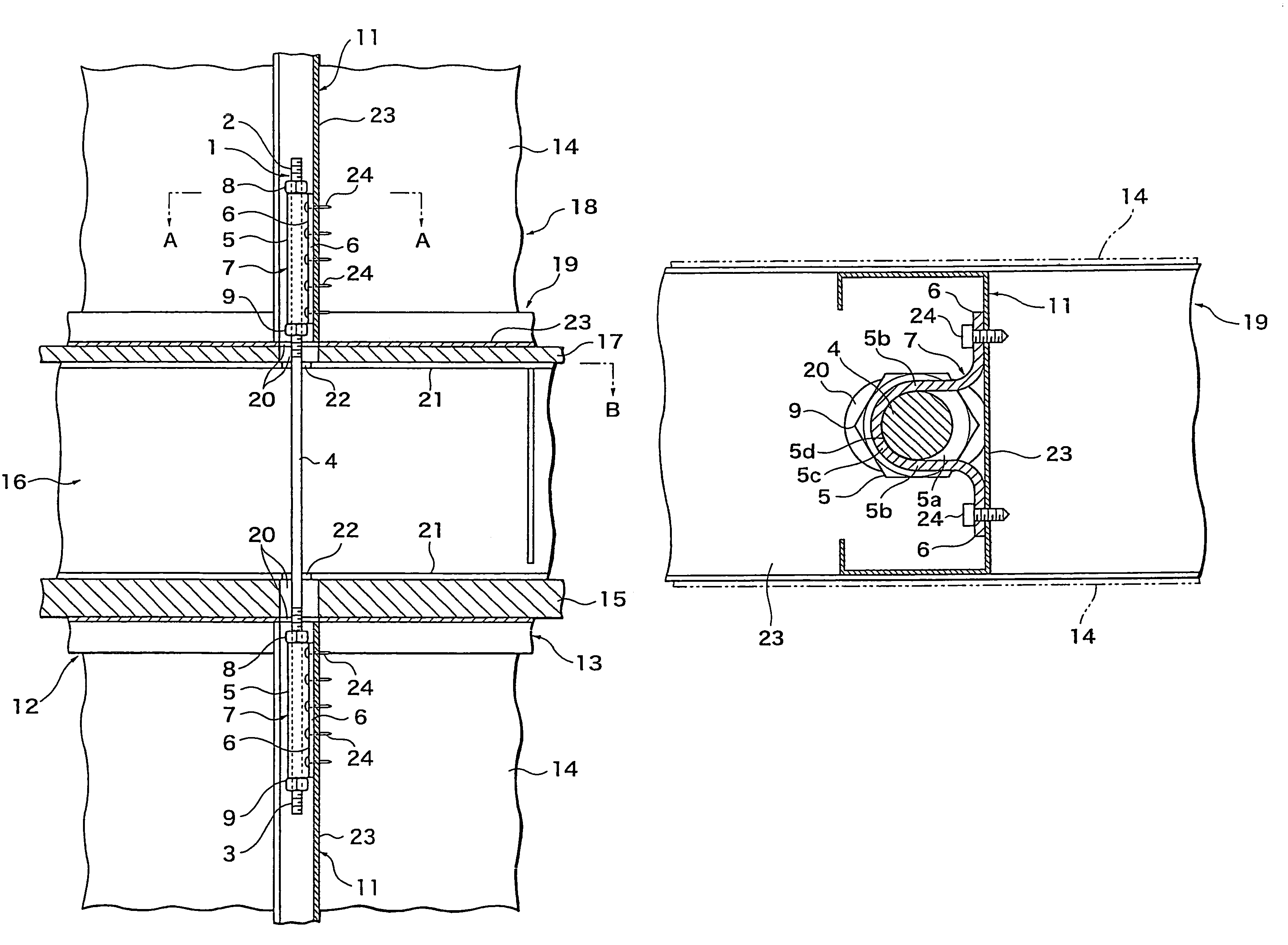
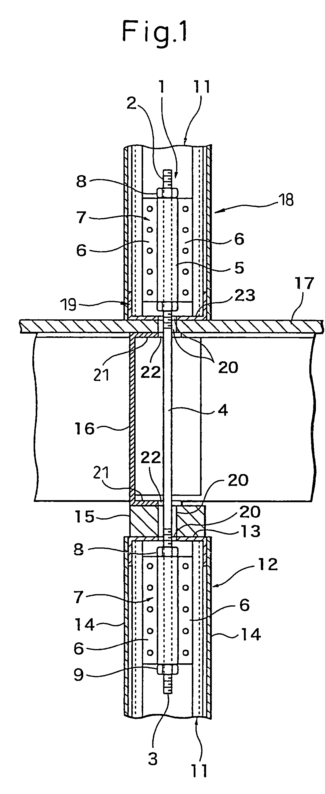
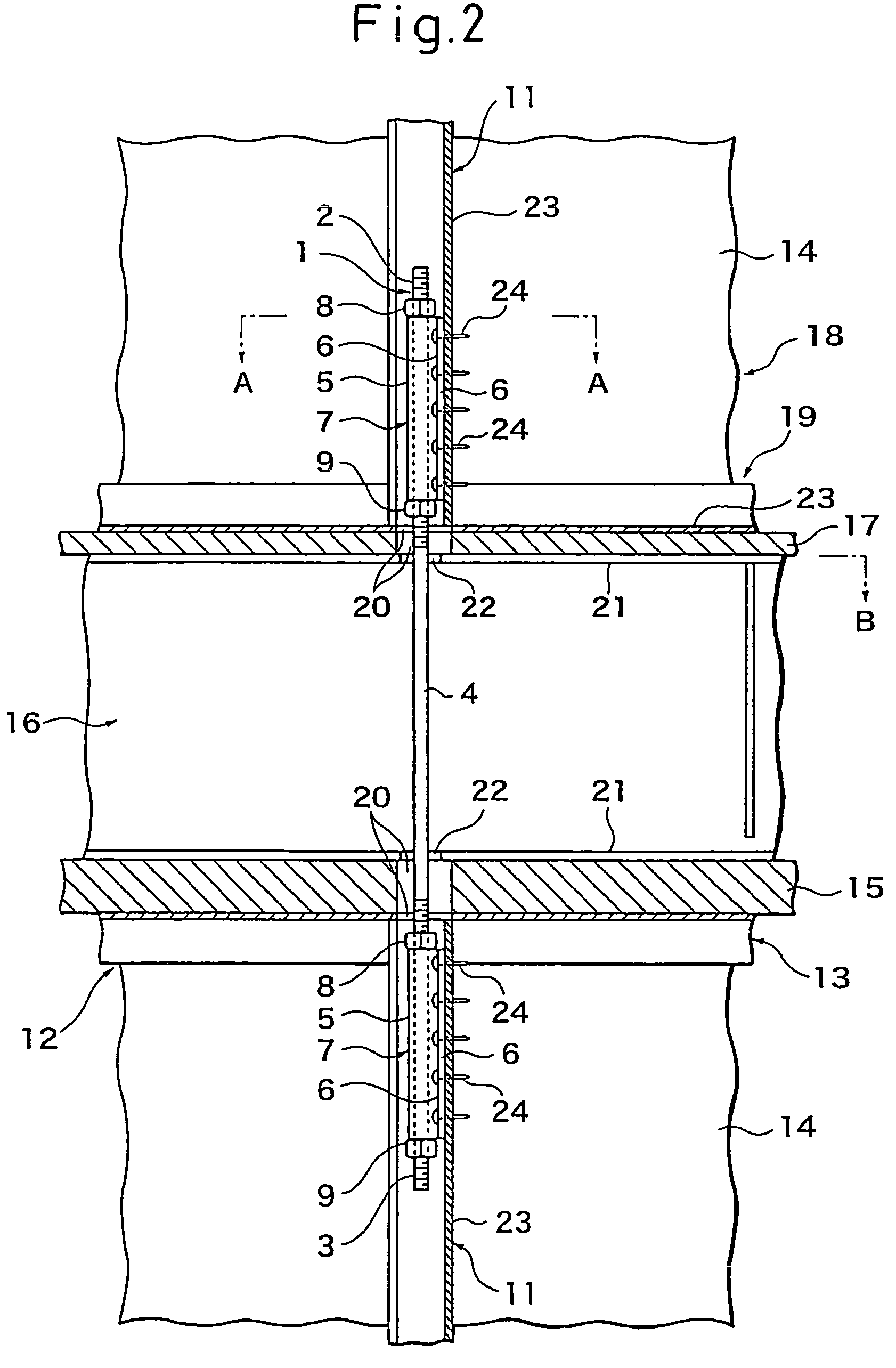
[0083]First, explaining a joint fitting between members of a first embodiment of the present invention with reference to FIG. 6(a), FIG. 6(b) and FIG. 7(a), FIG. 7(b), and FIG. 7(c), the illustrated joint fitting 1 between members is comprised of a single bolt having a length enabling it to be arranged vertically oriented bridging a vertical frame member of an upper floor wall panel etc. and a vertical frame member of a lower floor wall panel etc. and provided with male threaded parts 2 and 3 at its upper and lower ends in the case of constructing a building, in particular a steel house structure, and, at the two ends in the vertical direction, comprised of joint hardware 7 each comprised of a U-shaped part 5 having a continuous groove 5a in the vertical direction and joint flanges 6 extending in the vertical direction at the two sides, where the grooves 5a are engaged with the bolt 4,...


PUM

PropertyMeasurementUnit
circumferenceaaaaaaaaaa
outer circumferenceaaaaaaaaaa
thicknessaaaaaaaaaa

Abstract

A joint fitting 1 between members comprising a single bolt 4 having a length enabling it to be arranged vertically oriented bridging an upper floor vertical frame member and a lower floor vertical frame member at intervals along the axial direction. Joint hardware 7 is fastened to vertical frame members of the floors arranged at the upper floor side and lower floor side. Side opening grooves in the joint hardware 7 detachable receive the bolt. The attached joint hardware 7 is able to be fastened positioned along the longitudinal direction of the bolt 4. The joint hardware 7 is arranged at the upper and lower floors with the joint hardware being butted against vertical side surfaces of the vertical frame members 11 of the floors and fastened by drill screws 24 or other fasteners.

Description

TECHNICAL FIELD[0001]The present invention relates to a joint fitting between members connecting vertical frame members, horizontal frame members, floor joints, or roof truss chord members, and other members adjoining each other directly or spaced apart at upper and lower floors of buildings, in particular steel house structures, and to a joint structure and joining method of upper and lower floor vertical frame members using that joint fitting between members.BACKGROUND ART[0002]In the past, when connecting a vertical frame stud in an upper floor wall panel etc. and a vertical frame stud in a lower floor wall panel etc., a structure using joint hardware comprised of three pieces of hardware consisting of two pieces of hold down hardware and a set of a connection bolt and nuts, fastening the hold down hardware to the vertical frame stud in the upper floor wall panel, fastening the hold down hardware to the vertical frame stud in the lower floor wall panel, and connecting these hold ...

Claims


Application Information

Patent Timeline
Patent Type & Authority Patents(United States)
IPC IPC(8): E04B5/18G11B5/09E04B1/24E04B1/38E04B1/61G11B5/00G11B5/012G11B5/02G11B19/04G11B20/10G11B20/24
CPCE04B1/2403E04B2001/2418Y10T403/7045E04B2001/2484E04B2001/2448E04B1/08E04B1/58
Inventor FUJIHASHI, KAZUNORIKAWAI, YOSHIMICHITOHNAI, SHIGEAKITANAKA, HIROSHI
Owner NIPPON STEEL CORP
Why Eureka
Try Eureka