Fixation for a wind turbine blade to the hub
a technology of wind turbine blades and hubs, applied in the direction of propellers, propulsive elements, water-acting propulsive elements, etc., can solve the problems of fatigue, inability to work well with fibre-reinforced plastics, and appearance of technical problems
- Summary
- Abstract
- Description
- Claims
- Application Information
AI Technical Summary
Benefits of technology
Problems solved by technology
Method used
Image
Examples
first embodiment
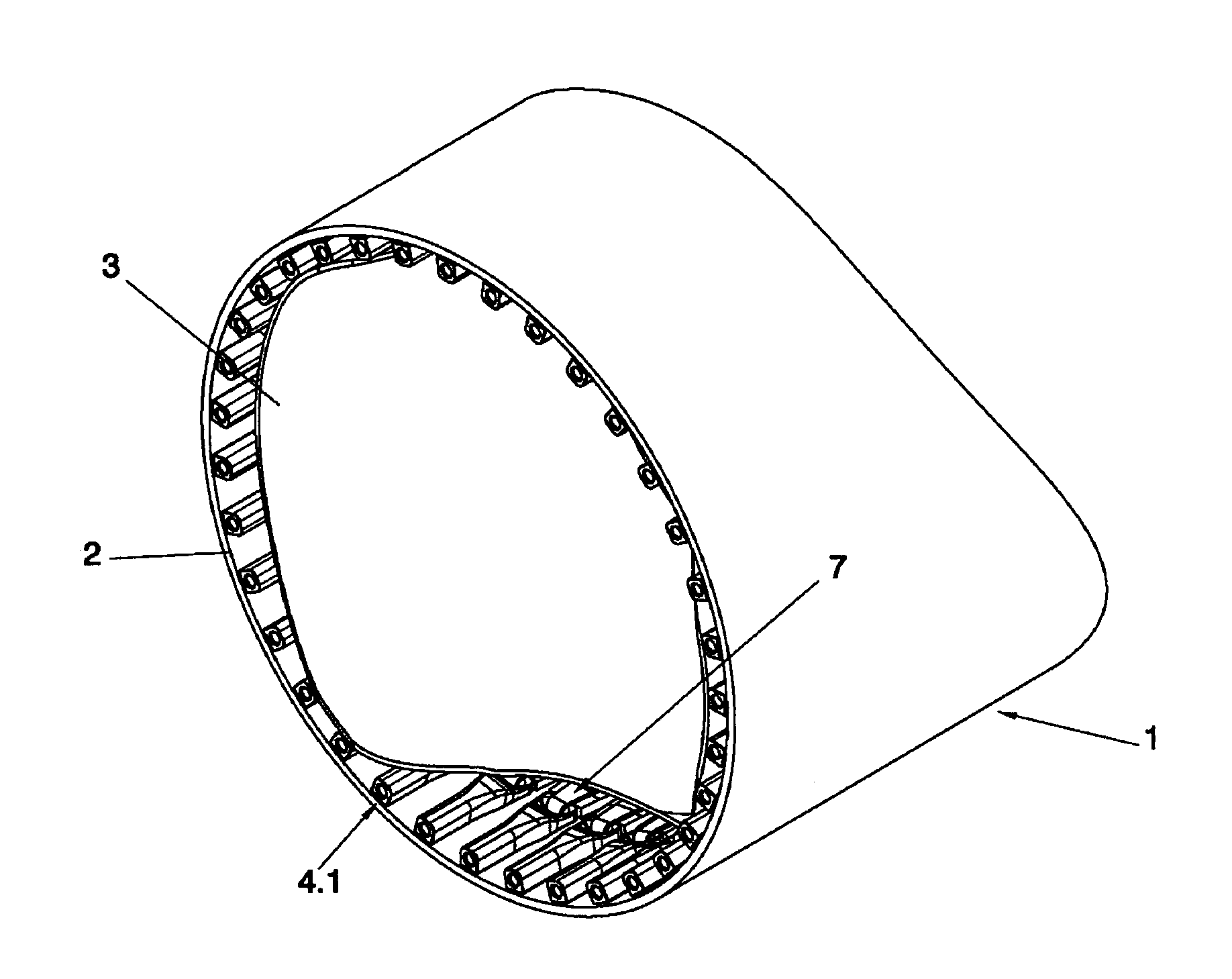
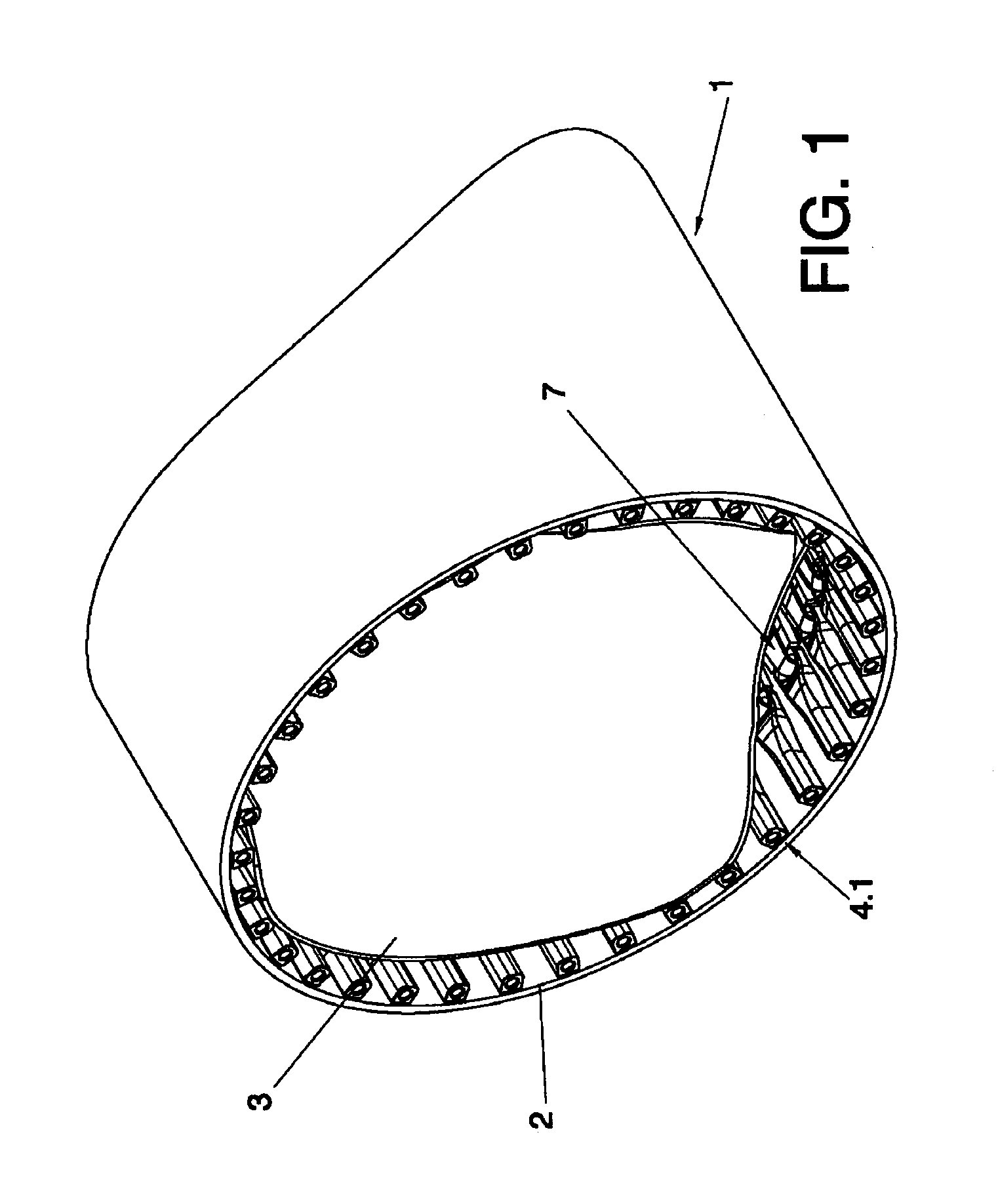
[0032]FIG. 1.—Shows a perspective view of a detail of the root of a blade wherein the inserts are situated, configured according to the insert, with the inserts spaced, in longitudinal disposal and gripped by the fibre bands between a lower sheet and upper laminated sheet.
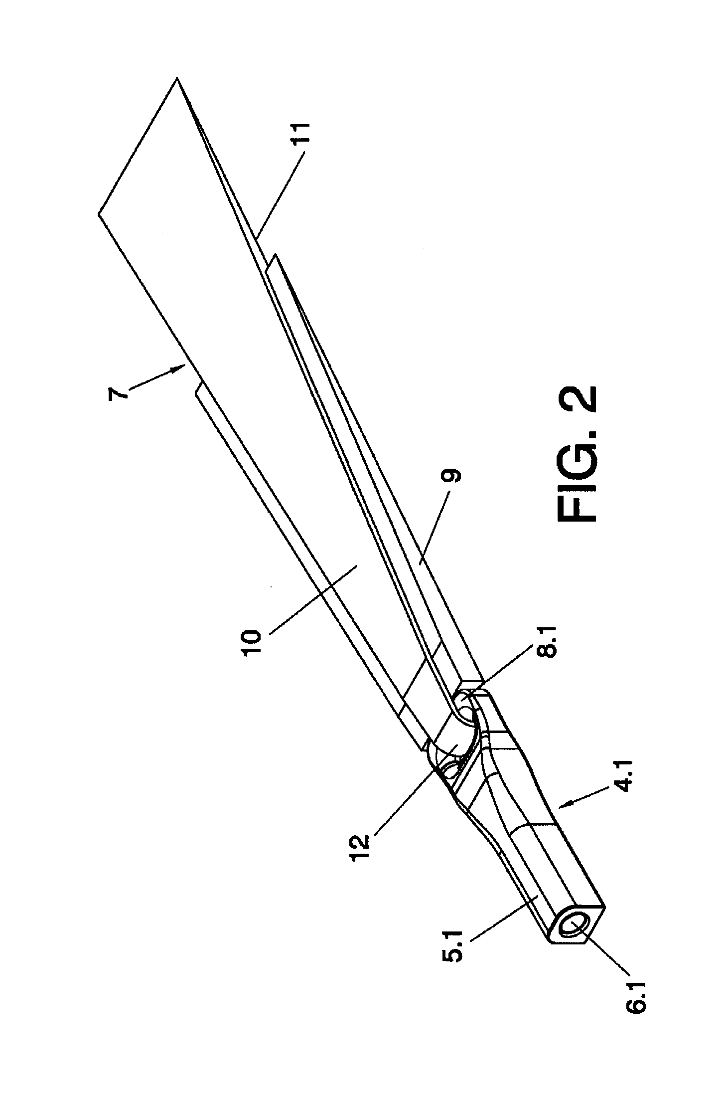
[0033]FIG. 2.—Shows a view of the embodiment of the insert of the previous figure gripped by the fibre band.
[0034]FIG. 3.—Shows a perspective view of only the insert of the previous figures.
second embodiment
[0035]FIG. 4.—Shows a perspective view of the joining insert.
[0036]FIG. 5.—Shows a view of the second embodiment representing the insert with the fibre band gripping the lateral gripping sectors.
[0037]FIG. 6.—Shows a perspective view of a detail of the root of a blade wherein the inserts configured according to the second embodiment are located, wherein insertion blocks situated between inserts have also been represented.
[0038]FIG. 7.—Shows an enlarged detail of the previous figure.
[0039]FIG. 8.—Shows a view similar to that of FIG. 1 wherein, unlike the former, the insertion blocks have been incorporated between inserts.
third embodiment
[0040]FIG. 9.—Shows a perspective view of a detail of the root of a blade wherein the inserts configured are located, where the insert appears in transversal disposal with respect to the longitudinal shaft of the blade.
[0041]FIG. 10.—Shows a view similar to that of the previous figure wherein the upper laminated sheet has been partially eliminated for a better view of the fibre bands which grip the inserts.
[0042]FIG. 11.—Shows a perspective view of the third embodiment, wherein the fibre band gripping the bushings which form the insert is observed, with the pin introduced in said bushings.
[0043]FIG. 12.—Shows a detailed view of FIG. 11 according to section A-A.
[0044]FIG. 13.—Shows a perspective view wherein the root of the blade and the internal structure or core of the blade is observed, wherein the third embodiment of the insert has been incorporated with the fibre band gripping the end of the internal structure of the blade.
[0045]FIG. 14.—Shows a perspective view wherein the roo...
PUM
 Abstract
Description
Claims
Application Information
 - R&D
- Intellectual Property
- Life Sciences
- Materials
- Tech Scout
- Unparalleled Data Quality
- Higher Quality Content
- 60% Fewer Hallucinations
Browse by: Latest US Patents, China's latest patents, Technical Efficacy Thesaurus, Application Domain, Technology Topic, Popular Technical Reports.
© 2025 PatSnap. All rights reserved.Legal|Privacy policy|Modern Slavery Act Transparency Statement|Sitemap|About US| Contact US: help@patsnap.com


