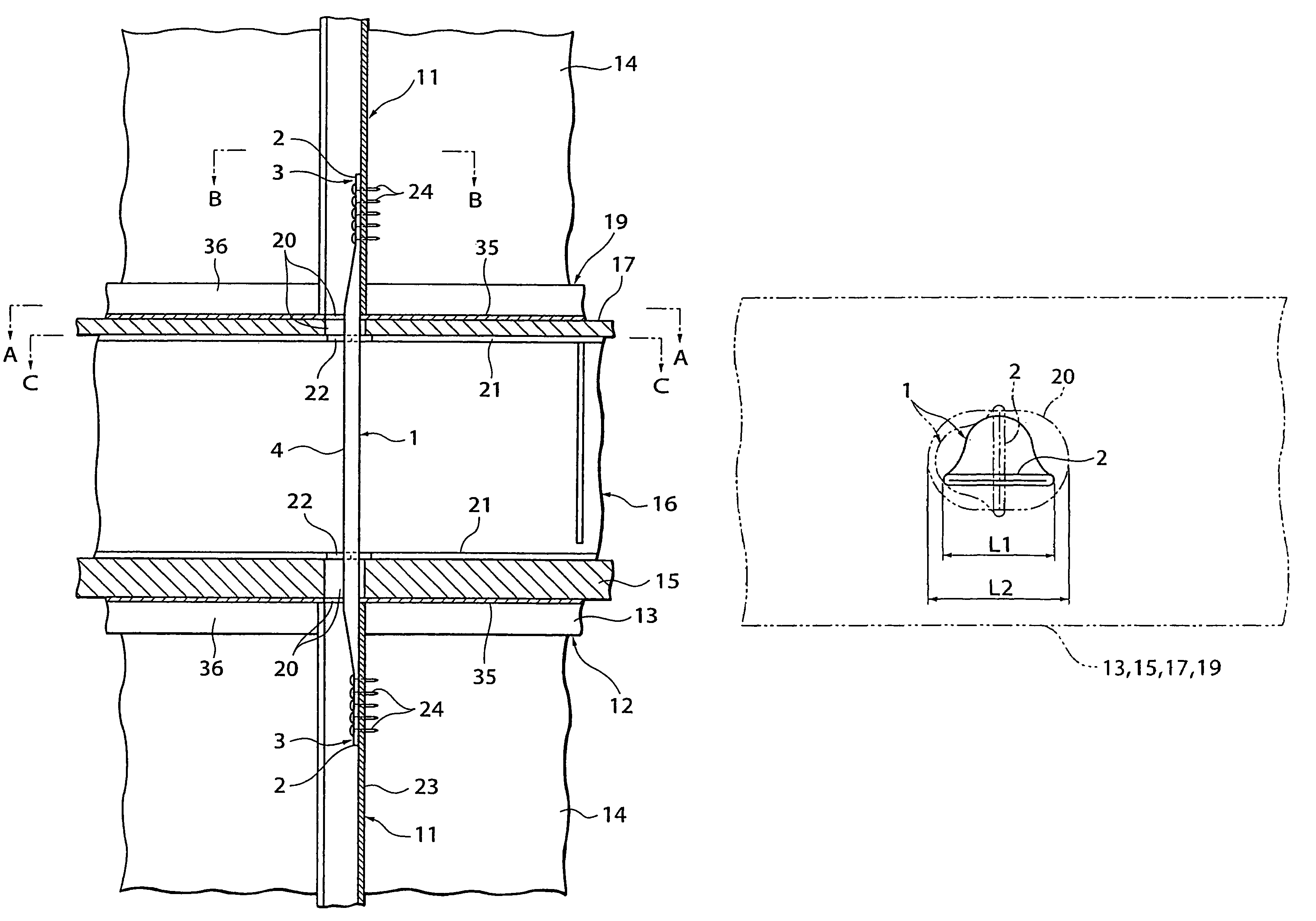
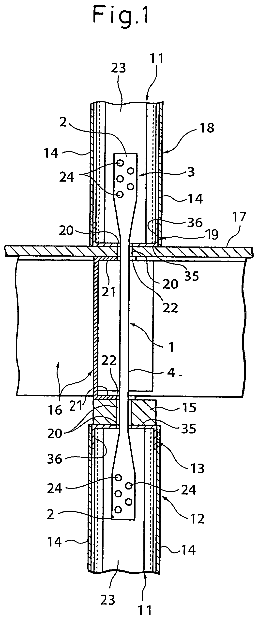
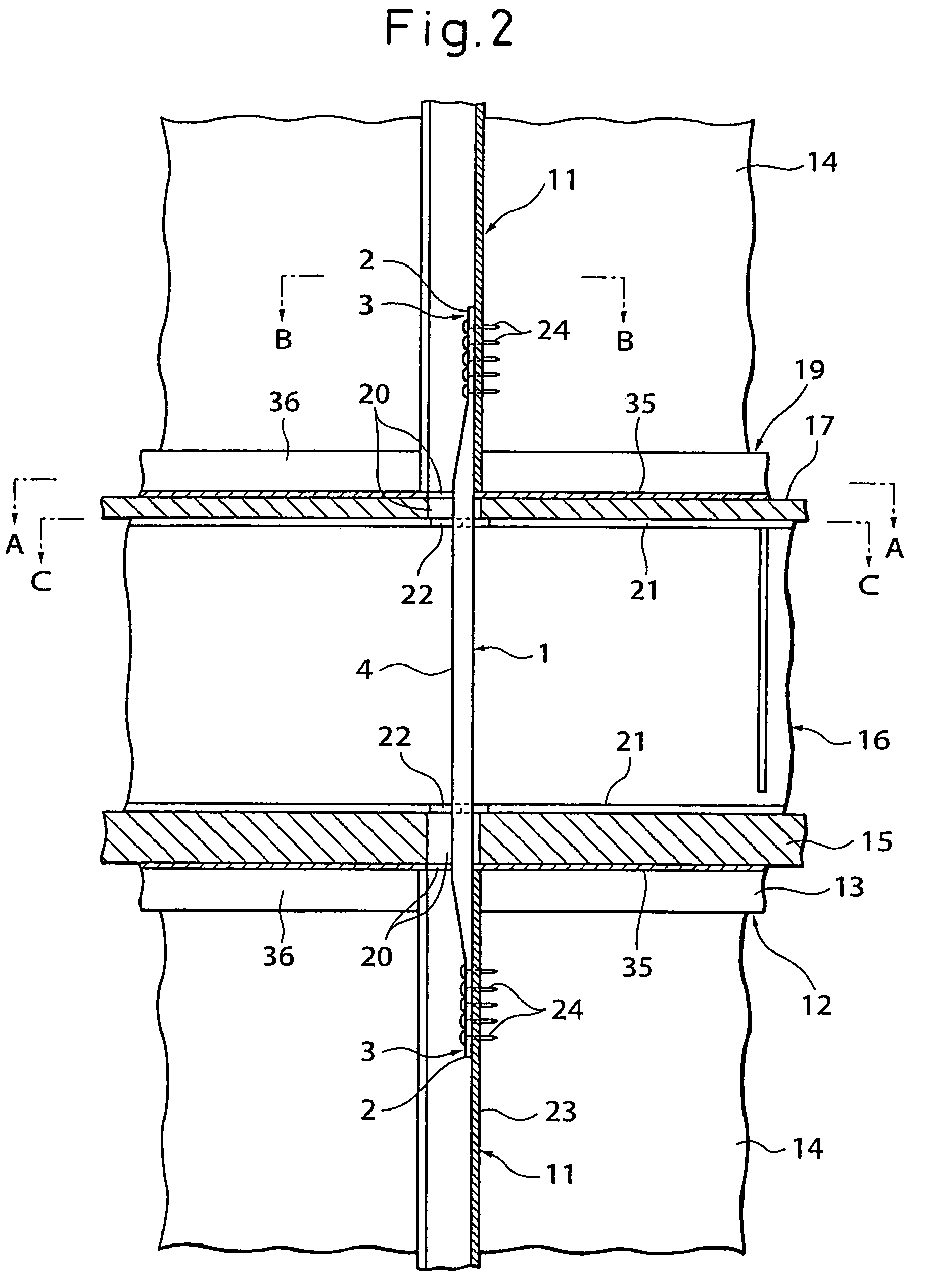
Joint fitting between members, joint structure of upper and lower floor vertical frame members, and method of joining
a vertical frame and joint technology, applied in the direction of towers, structural elements, building components, etc., can solve the problems of complex installation, high installation cost, and high level of installation ability, and achieve the effects of reducing width dimensions, large bending rigidity, and high general usability
- Summary
- Abstract
- Description
- Claims
- Application Information
AI Technical Summary
Benefits of technology
Problems solved by technology
Method used
Image
Examples
second embodiment
[0099]FIG. 8 and FIG. 9(a), FIG. 9(b), FIG. 9(c) show the joint fitting 1 between members of a second embodiment of the present invention and a joint structure of upper and lower floor vertical frame members using the same. The parts differing from the above embodiment is mainly the configuration of the joint fitting 1 between members, so these different parts will mainly be explained.
[0100]In this embodiment, the joint fitting 1 between members is comprised of a metal connection member body 4 made of a steel bar 7 and flat joint parts 3 at the two ends of the steel bar 7 obtained by welding W notched grooved joint plates 10 comprised of rectangular steel sheets having starting holes 5 at one end and having notched grooves 8 at the middle in the width direction at the other end, more specifically notched grooved joint plates 10 opened toward the ends at one end are used, a plurality of starting holes 5 for drill screws are provided at the other ends of the notched grooved joint plat...
third embodiment
[0102]FIG. 10 and FIG. 11(a), FIG. 11(b), FIG. 11(c) show a joint fitting 1 between members of a third embodiment of the present invention and a joint structure of upper and lower floor vertical frame members using the same.
[0103]The point of difference from the above embodiments is that the steel sheet joint plates 10 are not provided with notched parts. The surfaces of the joint plates 10 have the two ends of the steel bar 7 fastened to them by welding W. Starting holes 5 are provided at the two sides of this weld zone W. In this embodiment, since the joint plates do not have to be given notched grooves etc., it is possible to inexpensively fabricate a joint fitting 1 between members with a large rigidity of the joint plates 10.
[0104]Using such joint plates 10 is effective when it is possible to make the long side dimensions of the elongated through holes 20 provided at the upper floor and lower floor members (19, 17, 15, 13) relatively long. The rest of the configuration is simil...
fourth embodiment
[0105]FIG. 13 to FIG. 15(a), FIG. 15(b) show a joint fitting 1 between members and a joint structure of upper and lower floor vertical frame members using the same of a fourth embodiment of the present invention.
[0106]The joint fitting 1 between members of this embodiment is made of steel sheet bent to form a web 25 at the two sides of which flanges 26 are provided to form a groove cross-section steel material comprising a metal connection member body 4.
[0107]The parts of the web 25 at the two ends of the metal connection member body 4 are broadened. The flat parts formed by the web 25 there are formed with pluralities of starting holes 5 and made joint parts 3. The width dimension L1 of the web 25 at the parts of the joint parts 3 is made broader than the width dimension of the web 25 at the middle of the metal connection member body 4 in the vertical direction, the width dimension d1 of the flanges 26 of the middle part of the metal connection member body 4 in the vertical directi...
PUM
 Abstract
Description
Claims
Application Information
 - R&D
- Intellectual Property
- Life Sciences
- Materials
- Tech Scout
- Unparalleled Data Quality
- Higher Quality Content
- 60% Fewer Hallucinations
Browse by: Latest US Patents, China's latest patents, Technical Efficacy Thesaurus, Application Domain, Technology Topic, Popular Technical Reports.
© 2025 PatSnap. All rights reserved.Legal|Privacy policy|Modern Slavery Act Transparency Statement|Sitemap|About US| Contact US: help@patsnap.com


