Anti-reverse flow mechanism for centrifugal blowers

a centrifugal blower and reverse flow technology, which is applied in the direction of wind motors with parallel air flow, wind motors with perpendicular air flow, liquid fuel engine components, etc., can solve the problems of additional operational strain on the remaining operating blower, reducing the effectiveness of the cooling of the internal components of the machine,

Inactive Publication Date: 2006-10-31
REGAL BELOIT AMERICA
View PDF7 Cites 27 Cited by
  • Summary
  • Abstract
  • Description
  • Claims
  • Application Information

AI Technical Summary

Benefits of technology

[0008]The louvers have an airfoil-type profile in cross section, with tapered leading and trailing portions, and the louvers are pivotally mounted within the outlet of the blower housing adjacent their leading portions. In the open position, the airfoil profile of the louvers positions same substantially horizontally upon contact with the airflow from the impeller, and offers minimal resistance to the flow of air around the louvers and through the outlet. In the closed position, the louvers are positioned by gravity in an overlapping arrangement in which the louvers cooperate with one another and with the walls of the outlet to substantially block the outlet and prevent the reverse flow of air into the outlet from externally of the blower.
[0009]Thus, when a set of blowers according to the present invention is used for providing a flow of cooling air through a machine, if one of the blowers should fail, the louvers thereof automatically move by gravity to the closed position to block the flow of air through the outlet of the failed blower from externally of the machine. Thus, “reverse flow” of cooling air from outside of the machine through the outlet of the failed blower is prevented. In this manner, should one or more of the blowers fail, the normal flow of cooling air through the machine is not disrupted, and the remainder of the operating blowers continue to draw cooling air solely through the cooling air inlet of the machine and exhaust the heated exhaust air through the outlets of the operating blowers.
[0012]In another form thereof, the present invention provides, in combination, an enclosure having at least one inlet; and a blower mounted in the enclosure, the blower including a blower housing having an outlet; an impeller rotatable within the housing and positioned to generate an airflow through the at least one inlet of the enclosure to the outlet; at least two louvers movably mounted to the blower housing proximate the outlet, the louvers moveable between a first position in which the louvers are positioned by contact with the airflow upon rotation of the impeller in a substantially parallel relationship with respect to one another, and a second position in which the louvers are positioned by gravity in overlapping relationship with respect to one another to substantially block the outlet when the impeller is stationary; whereby in the first position, the louvers allow the airflow to pass through the outlet, and in the second position, the louvers substantially prevent passage of air through the outlet from externally of the blower housing.

Problems solved by technology

A problem with the foregoing arrangement is that if one of the blowers fails for any reason, the impeller within that blower becomes stationary, yet the outlet of the failed blower remains in airflow communication with the atmosphere externally of the machine.
The foregoing disrupts the normal flow of cooling air through the machine, thereby reducing the effectiveness of the cooling of the internal components of the machine, possibly leading to overheating.
Additionally, when a blower fails, disruption of the flow of cooling air places additional operational strain on the remaining operating blowers.

Method used


Image

  • Anti-reverse flow mechanism for centrifugal blowers
  • Anti-reverse flow mechanism for centrifugal blowers
  • Anti-reverse flow mechanism for centrifugal blowers

Examples


Embodiment Construction

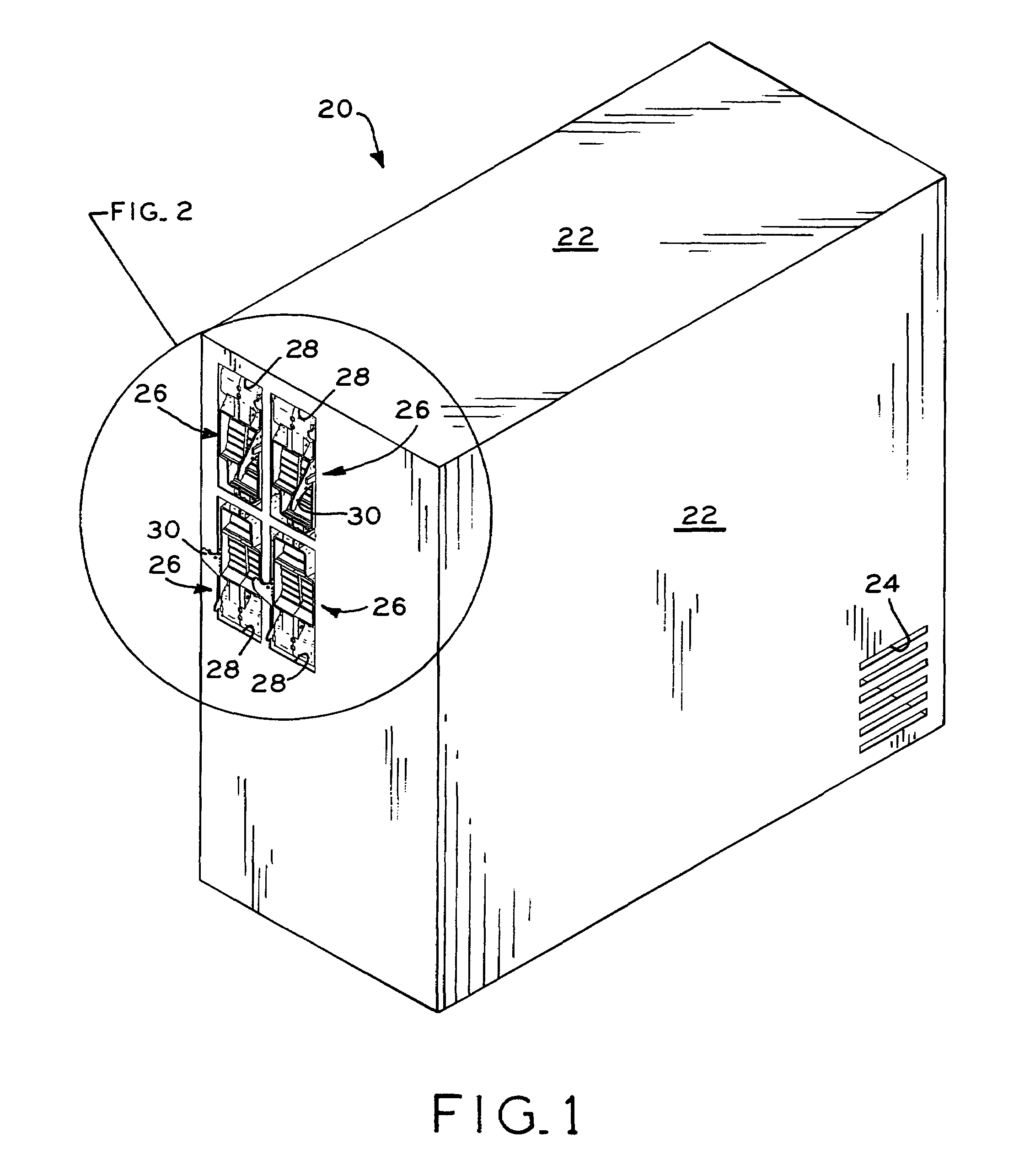
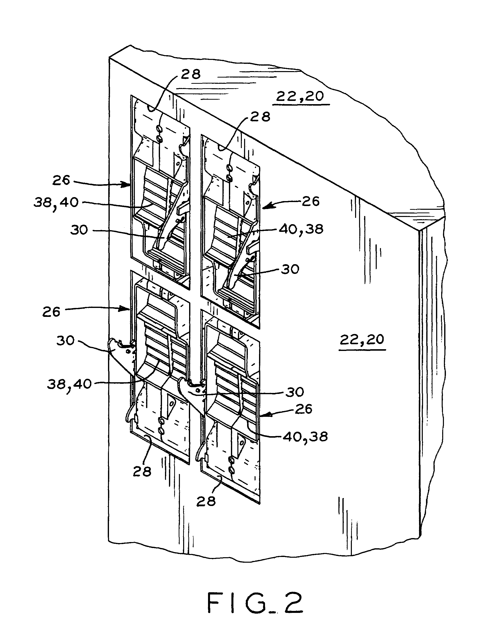
[0033]Referring to FIG. 1, electrical machine 20 is shown, which may be a computer server, for example, or any other machine which includes a housing having internal electrical components such as circuit boards and electric motors, for example, which generate heat during operation and must therefore be cooled by a flow of cooling air through the machine while the machine is operating. Machine 20 generally includes a box-shaped housing 22 having a cooling air inlet 24, which is shown in FIG. 1 in the form of a plurality of slots in housing 22. A plurality of blowers 26, four of which are shown in FIGS. 1 and 2, are mounted within corresponding blower cavities 28 in housing 22 of machine 20. Latches 30 are pivotally mounted to blowers 26, and releasably engage cooperating latching structure (not shown) disposed within blower cavities 28 to secure and lock blowers 26 within blower cavities 28 of machine 20. Although blowers 26 are sized and adapted to be inserted within blower cavities...


PUM


Abstract

A set of cooling air blowers for machines which require cooling air during operation. The blowers each include an outlet having an anti-reverse flow feature for preventing the flow of air into the blower from externally of the machine should the blower fail, thereby ensuring that the remaining operating blowers are able to maintain a normal and adequate flow of cooling air through the air inlet of the machine and outwardly through the outlets of the remaining operating blowers. Each blower generally includes a blower housing having an inlet, an outlet, and an internal cavity in which an impeller is rotatably disposed, the impeller driven by an electrical motor mounted within the blower housing. The outlet of each blower housing includes a plurality of louvers movable between a first, open position in which the louvers are positioned by contact with the airflow upon rotation of the impeller to allow heated exhaust air to exit the blower housing through the outlet, and a second, closed position in which the louvers are positioned by gravity to substantially block the outlet when the impeller is stationary.

Description

BACKGROUND OF THE INVENTION[0001]1. Field of the Invention[0002]The present invention relates to blowers for circulating cooling air through machines, and in particular, the present invention relates to blowers which include an anti-reverse flow mechanism.[0003]2. Description of the Related Art[0004]Many electrically-powered machines include a housing in which electrical components such as circuits and motors are contained. During running of the machines, the electrical components within the machines generate heat which must be continuously vented from the machines to cool the internal electrical components. Typically, such machines include one or more internal blowers, each including an electric motor connected to an impeller which is disposed within a blower housing, the blower housing having an inlet in airflow communication with the interior of the machine housing and an outlet in airflow communication with an opening in the machine housing. In operation, rotation of the impelle...

Claims


Application Information

Patent Timeline
Patent Type & Authority Patents(United States)
IPC IPC(8): F04D29/44F24F7/06F03D7/04F04D25/14H05K7/20
CPCF04D25/14H05K7/20172
Inventor PAULSEN, FREDERICK D
Owner REGAL BELOIT AMERICA
Why Eureka
Try Eureka