Mine ceiling drill bit and blade

a drill bit and ceiling technology, applied in the field of ceiling drill bits and blades, can solve the problems of failure of the blade, failure of the drill bit used to drill holes, and inability to reduce the force which the drilling machine applies to such drill bits, so as to prevent the deterioration of the cutting surface, reduce the thrust force, and reduce the resistance

Inactive Publication Date: 2006-09-05
THE SOLLAMI COMPANY
View PDF9 Cites 30 Cited by
  • Summary
  • Abstract
  • Description
  • Claims
  • Application Information

AI Technical Summary

Benefits of technology

[0010]The invention further provides for a cutting edge along the bridge between the walls with angled surfaces extending rearwardly from opposite sides of the cutting edge. The cutting edge of the bridge and the inner cutting edges along the inner walls help cut chunks of rock and other hard material loosed by the blade so that they may be subsequently drawn by a vacuum across the sloping surfaces of the bit body to the aperture therein and into the inner bore of the drill steel for removal from the drill site. Each of the cutting sides of the blade, therefore, has a forward cutting edge, an outer end cutting edge, and an inner cutting edge with the forward cutting edge connecting with the associated outer end cutting edge and the associated inner cutting edge.
[0011]During use, axial and radial forces are generated within the body of the blade and become concentrated at the corners thereof. These inner forces can cause the rapid deterioration of the hard metal forming the cutting edge beginning from the corners thereof. I have found that the provision of a first flat at the end of the forward cutting edge where it intersects the inner wall, and a second flat at the other end of the forward cutting edge where it intersects the outer end, will disburse those forces and prevent deterioration of these cutting surfaces. The inverted V-shape of the bridge at the bottom of the slot provides minimal resistance to removing the core portion left in the center of the cut. Since the center of the rotating axis has near zero surface speed the thrust forces are reduced due to the minimal edge provided at the top of the bridge.

Problems solved by technology

Where the cutting end of the drill bit is configured to maximize the drilling rate, the forces applied to the cutting edge of the blade are also maximized, which in turn can contribute to the failure of the blade.
The life expectancy of the drill bits used to drill the holes in the roofs of mines could be increased by reducing the penetration rate of a drill bit, however, there is no practical way of reducing the force which the drilling machines apply to such bits.
Another problem with existing drill bits is that the cutting blade thereof may remove chunks of rocks that may be relatively large compared to the diameters of the passageways through which those chips must move as they are drawn away from the blade.

Method used


Image

  • Mine ceiling drill bit and blade
  • Mine ceiling drill bit and blade
  • Mine ceiling drill bit and blade

Examples


second embodiment

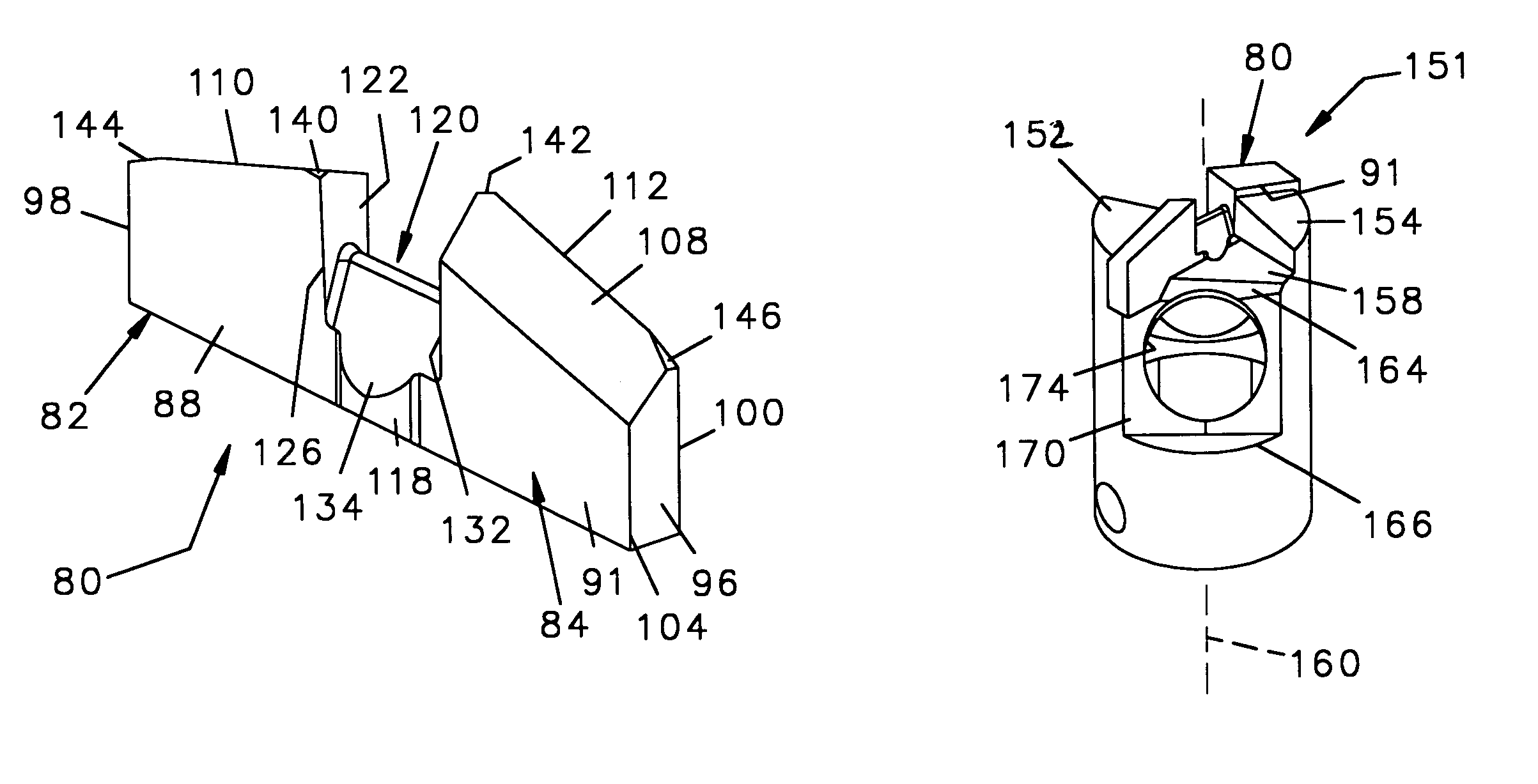
[0053]Referring to FIGS. 15 through 17 in which the invention is depicted, a drill bit 200 has a blade 202 attached to the bit body 150 previously described above. Blade 202 has cutting sides 204, 206, an axis 208, leading faces 210, 212 trailing faces 214, 216, and cutting surfaces 218, 220. Blade 202 also has inner relief panels 222, 224 and outer relief panels 226, 228.

[0054]Blade 202 differs from blade 80 in that blade 202 has a curved bridge 229 extending between the opposing parallel inner side walls 230, 232 creating a saddle configuration with sloping panels 234, 236 respectively to form a curved cutting edge 238. The curved cutting edge 238 of blade 202 breaks up large particles of hard material loosened from the center of the bore as the blade 202 continues its cut. By breaking up the large particles formed in the center of the bore, the particles are allowed to move across the angled portions 162, 164 of the bit body 150 to the apertures 174, 176 and be drawn by the vacuu...

third embodiment

[0055]a blade 240 in accordance with the invention, depicted in FIGS. 17–19, is similar to blade 80 previously described. Most of the elements of blade 240 are identical to the corresponding elements of the blade 80 and where such identical correspondence exists the elements of blade 240 are not described in this text and are identified on the drawings with indicia numbers identical to the corresponding indicia numbers of the blade 80 except they are primed.

[0056]The shape of both blades 80 and 240 are formed by forming tungsten carbide particles with a wax binder in a die and compressing them with a punch. The formed part is then cintered. The bridge 242 of the blade 240 is rounded at the center 244 as shown.

fourth embodiment

[0057]a blade 250, depicted in FIGS. 20–22, is similar to blade 202 previously described and the elements of blade 250 which are identical to those of blade 202 are not described herein but bear indicia numbers on the drawings identical to those of blade 202 except they are primed. In this embodiment the bridge 252 of the blade 250 has again been rounded at its center 254.


PUM

PropertyMeasurementUnit
axis of rotationaaaaaaaaaa
saddle shapeaaaaaaaaaa
stress reliefaaaaaaaaaa

Abstract

A drill bit consists of a bit body having a forward end and a slot in the forward end to hold a hardened cutting blade. The bit body has a table near the center of the blade to reduce the speed at which the drill bores into hard material. The blade has a central slot extending into the forward end thereof such that the slot defines inner side walls and a bridge extending between the inner side walls. The bridge has sloping sides the define a central cutting edge so as to cut particles of hard material accumulating in the slot. The inner side walls intersect the leading faces of the blade and form cutting edges which further cut particles loosened at the center of the cut. Also, relief flats relieve the concentration of forces at the ends of the primary cutting edges of the blade.

Description

[0001]The applicant claims priority from his co-pending provisional application filed Sep. 13, 2002 and assigned Ser. No. 60 / 410,851. The present invention relates to drill bits and the blades therefore, and specifically to an improved drill bit that can limit the rate of penetration of the bit into a hard surface to thereby reduce the breakage to the blade thereof, or can be designed to maximize the rate of penetration should that be desired.BACKGROUND OF THE INVENTION[0002]Drill bits for boring into rock to install roof bolts in underground mines and the like, have a hardened tungsten carbide blade mounted in a slot at the distal end of a tubular bit body. The bit body has access ports that communicate with the inner bore and a vacuum is drawn through the hollow bore of the drill bit to remove fines cut by the drill. In an alternate configuration, pressurized water may be forced through the inner bore of a hollow drill bit and out the ports near the blade to cool the blade and rem...

Claims


Application Information

Patent Timeline
Patent Type & Authority Patents(United States)
IPC IPC(8): E21B10/36
CPCE21B10/42E21B10/60E21B10/58Y10T408/906
Inventor SOLLAMI, PHILLIP A.
Owner THE SOLLAMI COMPANY
Why Eureka
Try Eureka