
Method and apparatus for safety switch

Active Publication Date: 2005-11-01
ADEMCO INC
View PDF16 Cites 61 Cited by
  • Summary
  • Abstract
  • Description
  • Claims
  • Application Information

AI Technical Summary

Benefits of technology

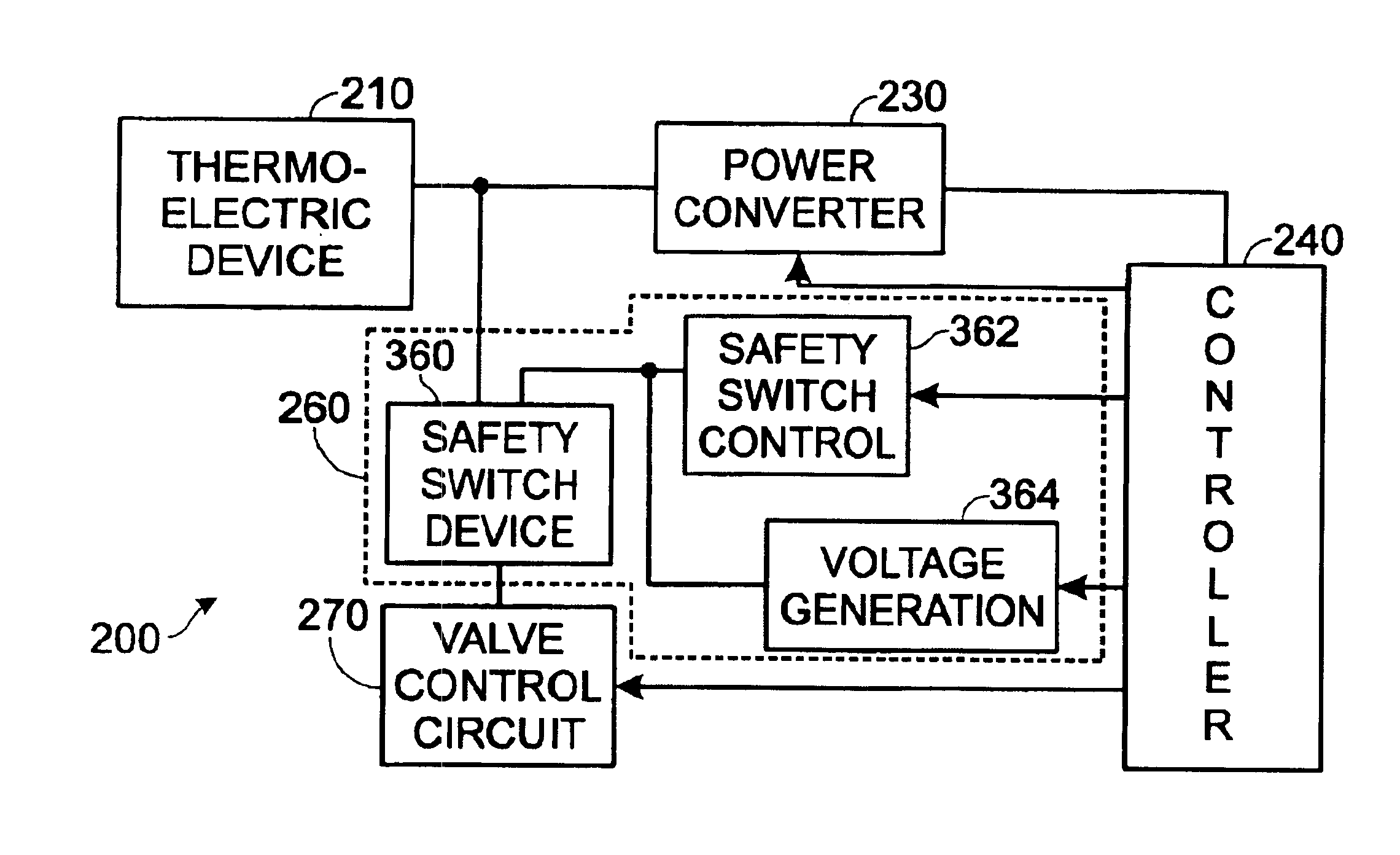
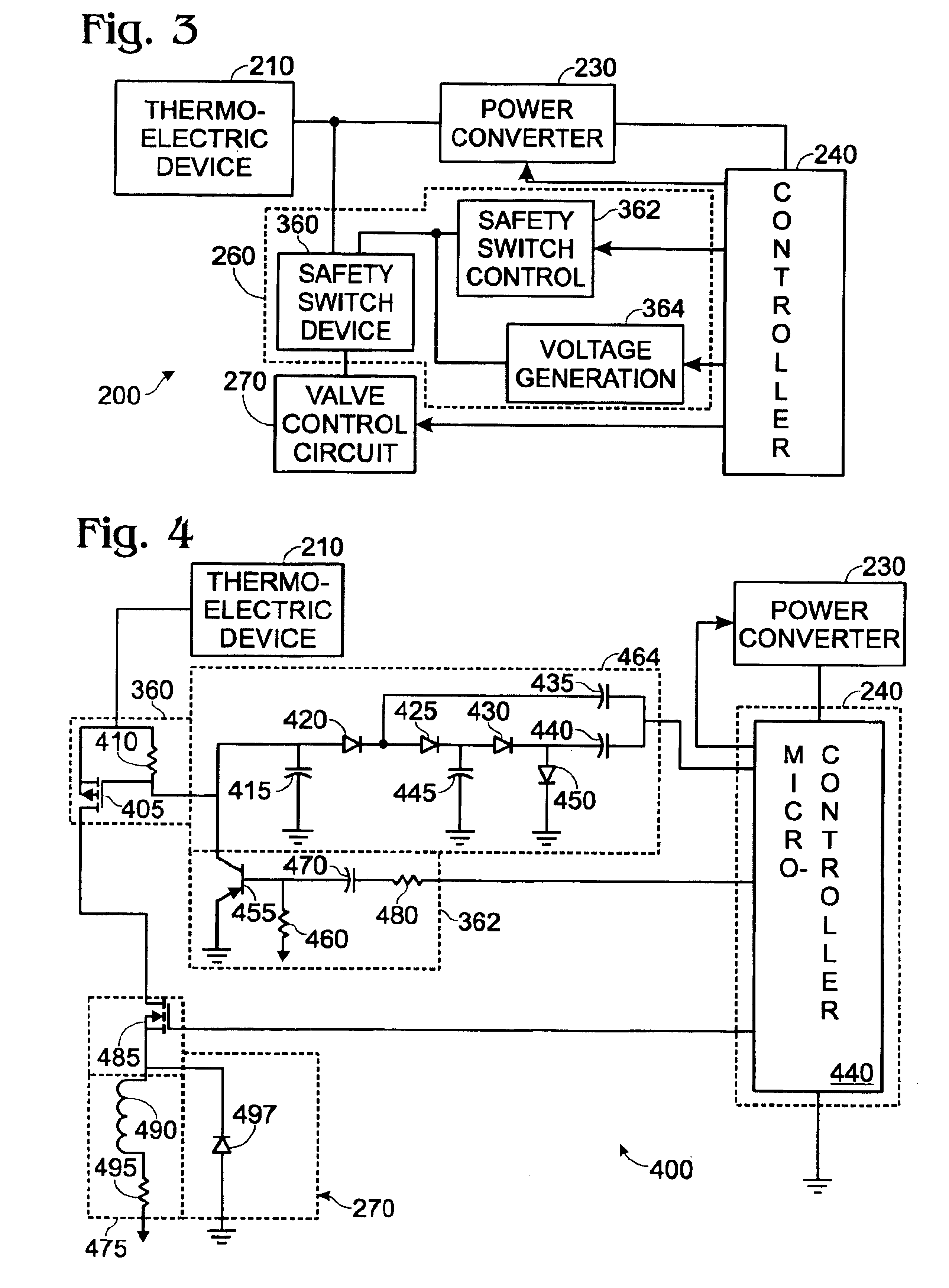
[0004]A circuit in accordance with the invention includes a safety switch device coupled with, and between, a thermally activated voltage source and a primary switch. The circuit also includes a safety switch control circuit coupled with the safety switch device and a controller circuit and a voltage generation circuit for closi

Problems solved by technology

In this regard, such approaches may not function as desired in the event of failure of the controller.
For example, if the controller were to fail due to a latch-up condition, the controller may cause both the primary and redundant switch to close when it is desired to have one, or both switches open.
Additionally, leakage current, due to moisture condensation or other factors, in a circuit that includes such switches may result in a sufficient voltage potential being generated to close the primary and / or redundant switch when it is desired to have one, or both of those switches open.

Method used


Image

  • Method and apparatus for safety switch
  • Method and apparatus for safety switch
  • Method and apparatus for safety switch

Examples


Embodiment Construction

[0010]In the following detailed description, numerous specific details are set forth in order to provide a thorough understanding of the invention. However, it will be understood that the present invention may be practiced without these specific details. In other instances, well-known methods, procedures, components and circuits have not been described in detail, so as not to obscure the present invention.

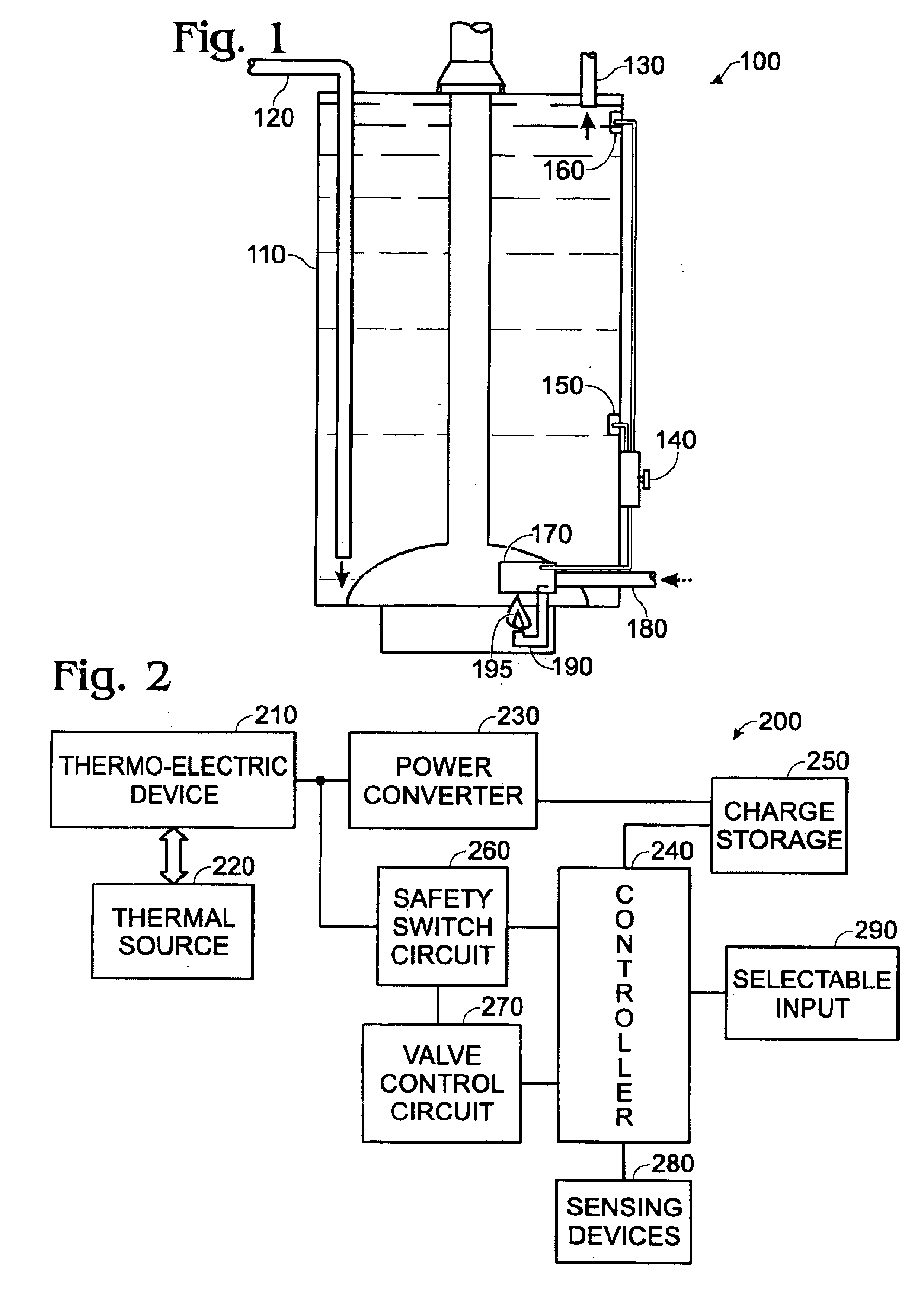
[0011]As was previously indicated, current approaches for control of gas-powered devices, such as appliances, may have certain drawbacks. Again, in this context, gas-powered typically means natural gas or liquid propane gas is employed as a primary fuel source. For the sake of illustration, the embodiments of the invention discussed herein will be described with reference to a water heater appliance. Of course, the invention is not limited in scope to use in a water heater, and other applications are possible. For example, embodiments of the invention may be employed in a gas-power...


PUM


Abstract

A circuit in accordance with the invention includes a safety switch device coupled with, and between, a thermally activated voltage source and a primary switch. The circuit also includes a safety switch control circuit coupled with the safety switch device and a controller circuit; and a voltage generation circuit for turning on the safety switch device. The voltage generation circuit is coupled with the safety switch control circuit, the controller circuit and the safety switch device, such that the controller circuit substantially controls operation of the voltage generation circuit, the safety switch control circuit, and a primary switch circuit that includes the primary switch.

Description

FIELD[0001]The present invention relates to gas powered appliances and, more particularly, to gas-powered appliances with thermally powered control circuits.BACKGROUND[0002]Gas-powered appliances typically have some form of control system included for controlling the operation of the appliance. In this context, a gas-powered appliance may be a water heater, a fireplace insert or a furnace, as some examples. Also in this context, “gas-powered” typically means natural gas or liquid propane gas is used as a primary fuel source. Current control systems used in gas-powered appliances typically have some form of redundant shut-off mechanism, which may be termed a safety switch, in addition to a primary shut-off mechanism.[0003]Such shut-off mechanisms typically take the form of a replicated electrical switch in series with a primary switch, where both the replicated and the primary switch are controlled by the same electrical control signal. A programmable controller, such as a micro-cont...

Claims


Application Information

Patent Timeline
IPC IPC(8): F24H9/20F24D18/00
CPCF24H9/2035F24H2240/08F24D2101/60F24D18/00F24H15/414F24H15/31F24H15/225
Inventor CHIAN, BRENTBIRD, DOUGLAS D.
Owner ADEMCO INC
Learn More