Irrigation dressing with a tubular dam

a tubular dam and irrigation dressing technology, applied in the field of wound healing, can solve the problems of constant re-infection, delay in healing process, and inability to perform dressing changes by patients alone,

Inactive Publication Date: 2005-11-01
ANGIODYNAMICS INC
View PDF11 Cites 100 Cited by
  • Summary
  • Abstract
  • Description
  • Claims
  • Application Information

AI Technical Summary

Benefits of technology

[0012]In accordance with a preferred embodiment of the invention, a wound shield and irrigation dressing system is provided to be worn on ambulatory patients for protecting and enclosing wounds. The wound shield allows for frequent irrigation of the wound with an irrigation solution and alternate frequent drying of the wound, while also providing for drainage of the irrigation solution and selective application of a vacuum to the wound.

Problems solved by technology

It is well known that gauze type dressings are not only messy, but result in constant re-opening of the wounds when the dressings are changed, which could cause infections and delay the healing process.
Further, dressing changes usually cannot be performed by the patient alone.
They are often quite painful to the patient, expensive, and not conducive to providing frequent irrigation of the wound with medical solutions.
Although the wound shield described above is preferred over gauze dressings, the foam rubber dam is too rigid for good sealing qualities.
Further, the overall wall depth of the device is too shallow to accommodate adequate irrigation solution volumes.
Lastly, the dam often comes into contact with the wound thus disrupting the healing process.
Although the wound dressing is modestly successful in treating patients, the device requires a fair amount of readjustment after it is installed on the patient because the dressing twists and bends with movement of the patient.
This is primarily due to a lack of flexibility in the wound shield.
Further, the device tends to buckle in the middle due to a lack of cross-sectional rigidity in the inflatable dam section.
This causes leakage from under the wound shield as well as undesirable contact between the wound and the window.

Method used


Image

  • Irrigation dressing with a tubular dam
  • Irrigation dressing with a tubular dam
  • Irrigation dressing with a tubular dam

Examples


Embodiment Construction

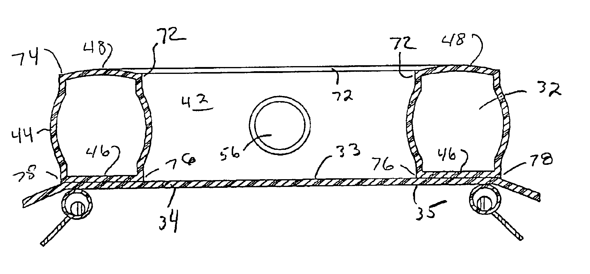
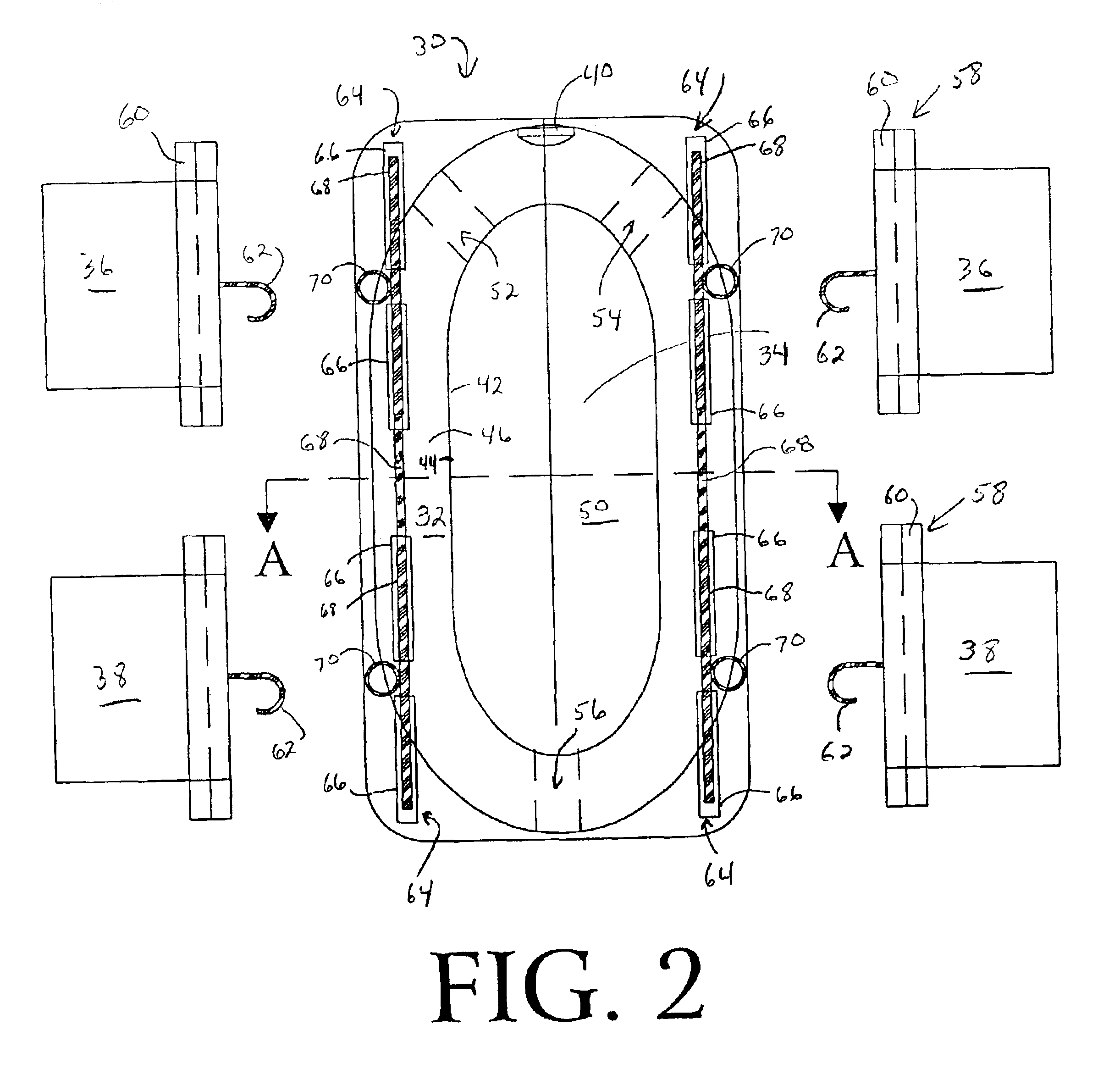
[0031]Referring now to the drawings wherein the showings are for the purpose of illustrating the preferred embodiments of the invention only, and not for purpose of limiting same, FIGS. 2-4 show a wound shield 30 including a hollow tubular inflatable dam 32, and a clear plastic window 34 attached to the dam 32. Dam 32 is formed of an inner peripheral surface or wall 42 which defines and surrounds a central opening 50. Dam 32 also includes an outer peripheral surface or a wall 44 connected to inner peripheral surface 42 by a rear or bottom body-engaging surface 48 and a front or top surface 46.

[0032]Dam 32 is provided with an irrigation aperture 52 extending from outer peripheral surface 44 through inner peripheral surface 42. Aperture 52 is adapted to receive or otherwise couple with an irrigation tube for providing communication between an irrigation system and central opening 50. Typically, the irrigation system provides an irrigation solution with medicinal characteristics for co...


PUM


Abstract

An irrigation dressing is provided including a hollow inflatable tubulardam with a central opening adapted to surround the wound of the individual. A semi-hard resilient clear plastic window is attached to the dam, such that the central opening is completely enclosed on a front surface of the dam. The dressing includes an inner peripheral ridge and an outer peripheral ridge extending beyond a bottom or back body-engaging surface of the dam which facilitates drawing a vacuum. A plurality of connectors are attached to a front planar face surface of the clear plastic window. At least one connector is pivotable about an axis parallel to the front planar surface of the window. A self-sealing plug is disposed inside the dam so that the dam can be inflated to selected pressures using an associated hypodermic needle or the like.

Description

FIELD OF THE INVENTION[0001]The present invention relates generally to medical treatment of wounds, and more particularly to an improved wound shield and irrigation dressing for treating wounds to promote the overall healing process and to discourage enteric fistula and wound infections.BACKGROUND OF THE INVENTION[0002]Wound shields for treating enteric fistula and wound infections are known. The express purpose of these prior devices is to provide an irrigation dressing for patients as a replacement for the typical gauze type dressings. It is well known that gauze type dressings are not only messy, but result in constant re-opening of the wounds when the dressings are changed, which could cause infections and delay the healing process. Further, dressing changes usually cannot be performed by the patient alone. They are often quite painful to the patient, expensive, and not conducive to providing frequent irrigation of the wound with medical solutions.[0003]One known prior art irrig...

Claims


Application Information

Patent Timeline
Patent Type & Authority Patents(United States)
IPC IPC(8): A61F13/00A61F15/00
CPCA61F13/00987A61F15/008A61F2013/00165A61F2013/0017A61F2013/00174
Inventor STEVENS, ROBERT C.
Owner ANGIODYNAMICS INC
Why Eureka
Try Eureka