System for monitoring connection pattern of data ports

a data port and connection pattern technology, applied in the field of cabled systems, can solve problems such as the difficulty of providing a dedicated conductor for connectivity-scanning purposes

Inactive Publication Date: 2005-11-01
COMMSCOPE TECH LLC
View PDF26 Cites 169 Cited by
  • Summary
  • Abstract
  • Description
  • Claims
  • Application Information

AI Technical Summary

Benefits of technology

[0015]Initially, all of the socket contacts are at low state with no signal being sent to them by the output module. To monitor the connectivity of the various ports, the micro-controller causes the designated first output driver to send out a pulse signal to the socket contact which the micro-controller has designated as the first contact. This places the first socket contact at a high state, and consequently, also places the first latch in the input module at the high state. After sending out the signal, the micro-controller scans the input module for a latch hav

Problems solved by technology

Although this principle is well known, in the modern era where many of the standardized cables such as RJ11 and RJ45 are used, it is difficult to provide this dedicated conduct

Method used


Image

  • System for monitoring connection pattern of data ports
  • System for monitoring connection pattern of data ports
  • System for monitoring connection pattern of data ports

Examples


Embodiment Construction

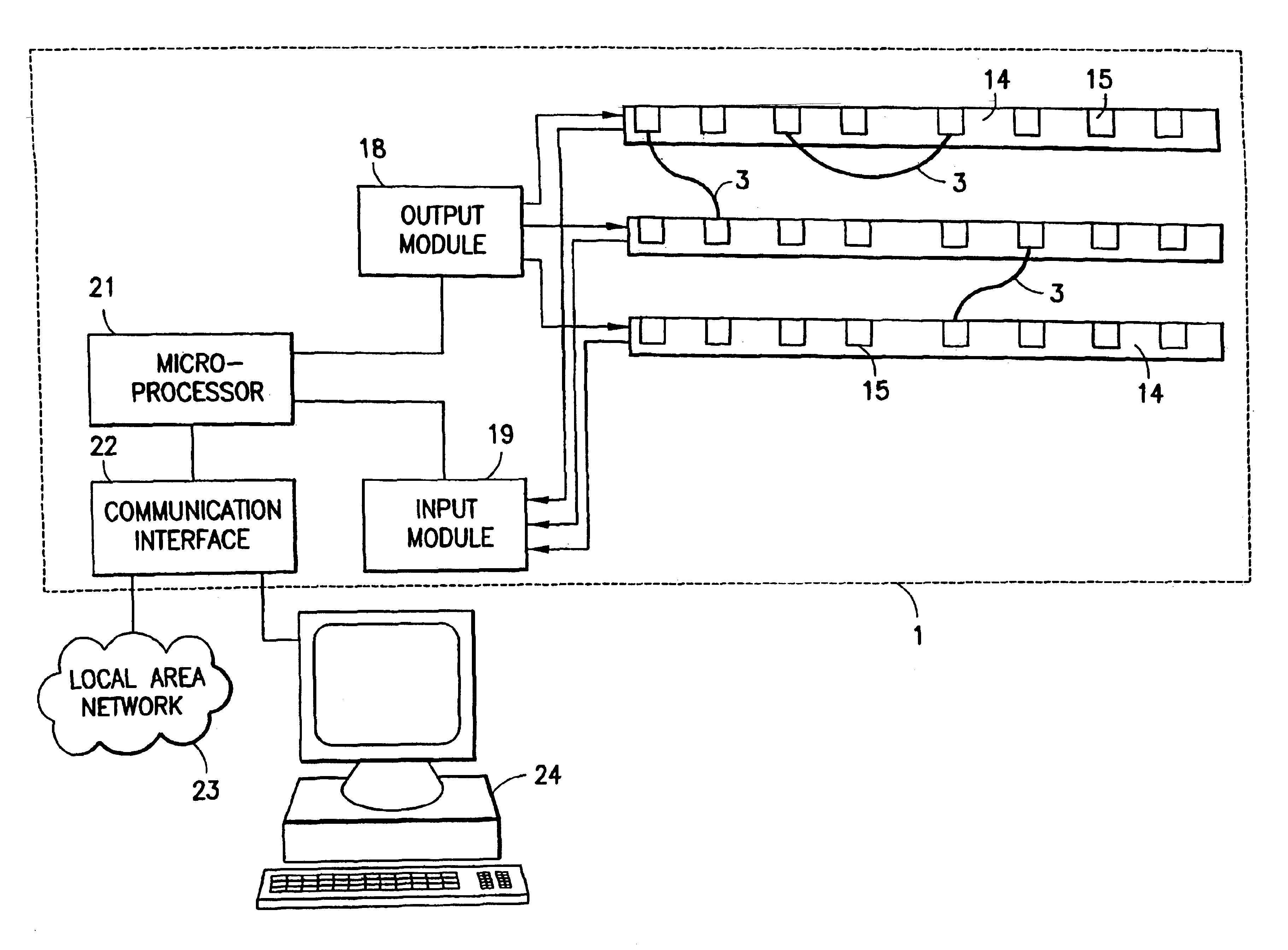
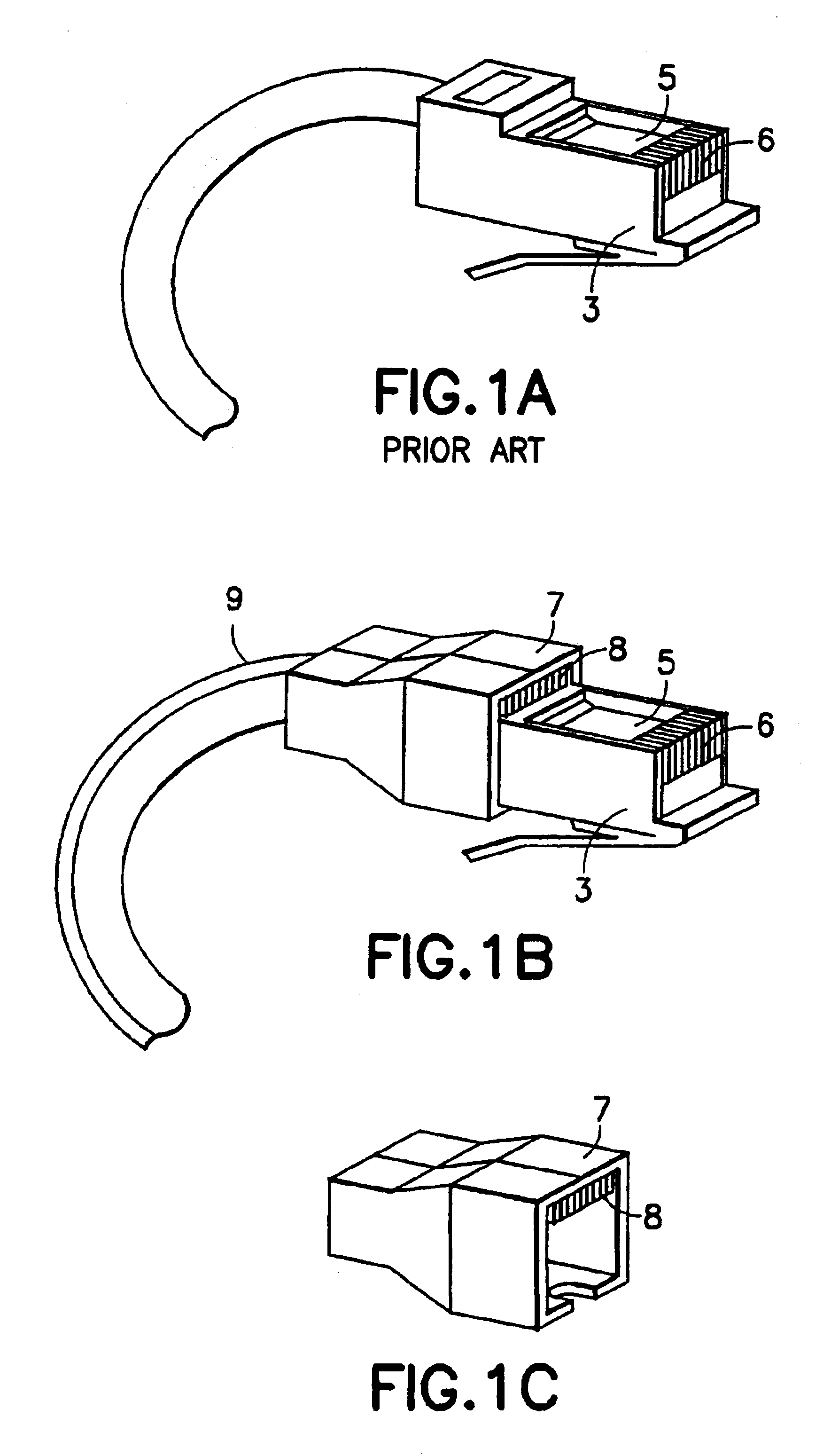
[0025]In order to electronically determine the connectivity between one port to another, it is generally well understood that an electrical conductor needs to connect one port to the other. Although this principle is well known, in the modern era where many of the standardized cables such as RJ11 and RJ45 are used, it is difficult to provide this dedicated conductor for connectivity-scanning purposes because each of the wires within the cable is used for a standardized purpose which may interfere with the connectivity-scanning operation. Although it may be possible to share an existing wire in the cable for the scanning operation, this would require additional circuitry for differentiating between the signals used for the scanning purposes and the signals used for other purposes such as data transfer. Moreover, in many cases, it may be impossible to effectively share an existing wire or conductor.

[0026]In the present connectivity monitoring system, a dedicated conductor which may be...


PUM


Abstract

The present invention determines and monitors the connection pattern of data ports which are connected by multiconductor cables without requiring special patch cables or patch panels. An adapter jacket having an external contact is placed over a standardized cable such as an RJ45 cable which connects the data ports. An adapter board having a plurality of socket contacts is placed adjacent a plurality of data ports. An output and input module are coupled to the socket contacts. A micro-processor which is coupled to the output and input module scans the socket contacts to determine the connection pattern of the data ports.

Description

[0001]The present application is a divisional application of U.S. patent application Ser. No. 09 / 525,543, filed Mar. 14, 2000, entitled SYSTEM FOR MONITORING CONNECTION PATTERN OF DATA PORTS, which issued as U.S. Pat. No. 6,684,179 on Jan. 27, 2004, the contents of which are hereby incorporated by reference.FIELD OF THE INVENTION[0002]The present invention relates to the field of cabled systems and related computer peripheral devices, and more particularly to a system and method for determining interconnection pattern of data ports without requiring special patching cables or patching panels.BACKGROUND OF THE INVENTION[0003]The problems of tracking the interconnection pattern among the various ports in a local area network are well known to those skilled in the art. At least one system which deals with this problem is described in the U.S. Pat. No. 5,483,467 entitled “Patching Panel Scanner”. The patent describes a patching panel scanner which automatically and continuously senses t...

Claims


Application Information

Patent Timeline
IPC IPC(8): G06F13/00G06F15/00H04L12/26H04Q1/14
CPCH04L12/2602H04L43/00H04Q1/136H04Q2201/802
Inventor DAVID, SOLOMON I
Owner COMMSCOPE TECH LLC
Why Eureka
Try Eureka