Mobile agricultural machinery

a technology of agricultural machinery and mobile devices, which is applied in the field of mobile agricultural machines, can solve the problems of degrading the turning performance at the bare end area of a wet rice field, changing the reaping height, etc., and achieves the effects of improving travel performance, reducing ground contact pressure, and easy maintenance of longitudinal balan

Inactive Publication Date: 2005-11-08
YANMAR CO LTD
View PDF15 Cites 37 Cited by
  • Summary
  • Abstract
  • Description
  • Claims
  • Application Information

AI Technical Summary

Benefits of technology

[0003]This invention relates to a combine, wherein right and left travel crawlers 3 and 4 supported by drive sprockets 39 and tension rollers 42 are installed to the right and left track frames 1 and 2 through track rollers 40, right and left track frames 1 and 2 are installed to this machine through crawler elevation arms 31 and 32 in a manner where the elevation action is controllable, and tension rollers42 are installed in the ground contact direction of travel crawlers 3 and 4 in a movable manner. Thus in this combine, the longitudinal ground contact length of travel crawlers 3 and 4 can be extended by movement of tension rollers 42 even if the elevation control action is performed to lower track frames 1 and 2 when, for example, a travel surface is soft like a wet rice field where the amount of penetration of travel crawlers 3 and 4 is large. Consequently, the longitudinal balance can be easily maintained by minimizing the longitudinal shift of the center of gravity of the machine body on the ground contact surface of travel crawlers 3 and 4, ground contact pressure can be lowered because of an increase in the ground contact area of travel crawlers 3 and 4, the amount of penetration of travel crawlers 3 and 4 can be reduced to easily achieve an improvement in travel performance such as a direction change, and the longitudinal ground contact length of travel crawlers 3 and 4 on a hard travel surface, such as a dry rice field and an agricultural road, can be reduced to secure the specified turning performance.
[0004]In this combine, track frames 1 and 2 are provided with link mechanisms 47 in a swingable manner, and link mechanisms 47 are provided with tension frames 44 for installing tension rollers 42 in an adjustable manner. Thus tension rollers 42 are easily movable in a direction for lowering track frames 1 and 2 while keeping track frames 1 and 2 away in an extended direction, the longitudinal ground contact length of travel crawlers 3 and 4 can be easily increased or decreased by shifting tension rollers 42 without changing the perimeter of travel crawlers 3 and 4, and simplification of the tension structure of travel crawlers 3 and 4 with improvement of travel performance can be easily achieved.
[0005]In this combine, tension frames 44 for installing tension rollers 42 in an adjustable manner are moved in linkage with the elevation control action of crawler elevation arms 31 and 32. Thus the ground contact length of travel crawlers 3 and 4 can be increased or decreased by shifting tension rollers 42 in a direction opposite the longitudinal movement of track frames 1 and 2 through an elevation control action. The change in the ground contact pressure of travel crawlers 3 and 4 associated with the elevation control action can be easily reduced, conventional problems caused by the elevation control action can be easily eliminated, and an improvement in the travel performance, such as turning ability at the bare end area of the farm, can be achieved.

Problems solved by technology

There are, however, problems where a shift in the center of gravity of the machine body toward the rear side of the lateral ground contact width of the travel crawler results in a tilting of the machine body backward, followed by the elevation of the moving section in front of the machine body, thus leading to a change in the reaping height, as well as problems where the backward shift in the center of gravity of the machine body increases the ground contact pressure on the rear side of the travel crawler and the backward travel facilitates the rear sides of the travel crawlers to penetrate into the earth, thus degrading the turning performance at the bare end area of a wet rice field.

Method used


Image

  • Mobile agricultural machinery
  • Mobile agricultural machinery
  • Mobile agricultural machinery

Examples


Embodiment Construction

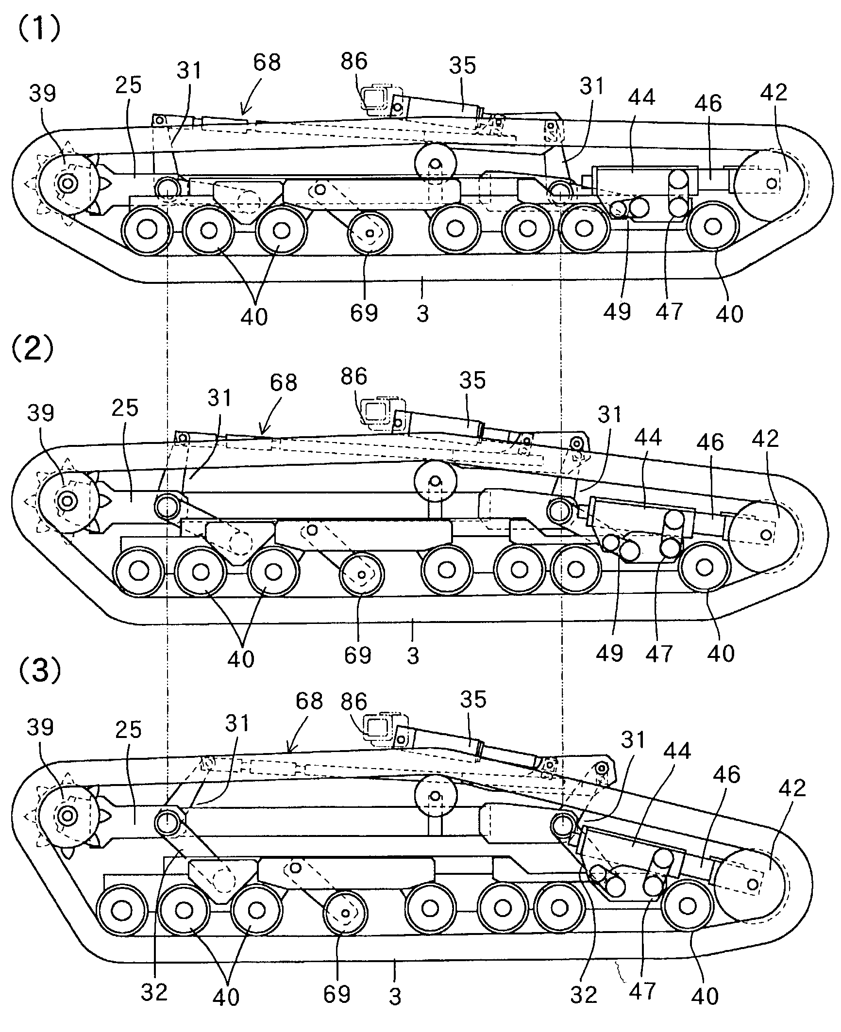
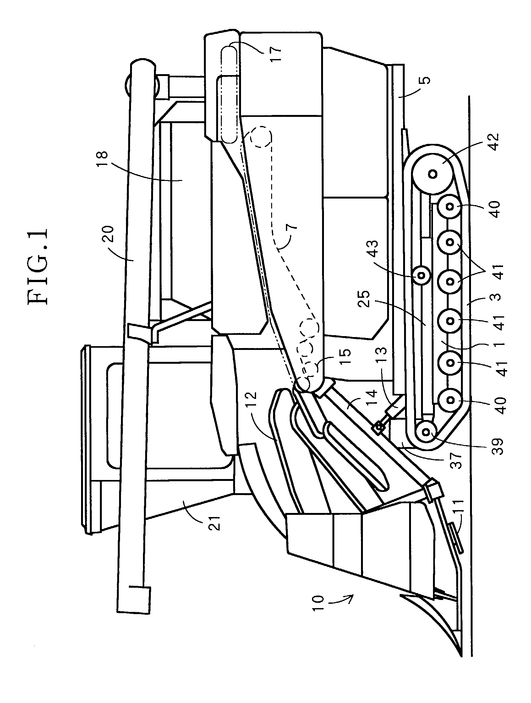
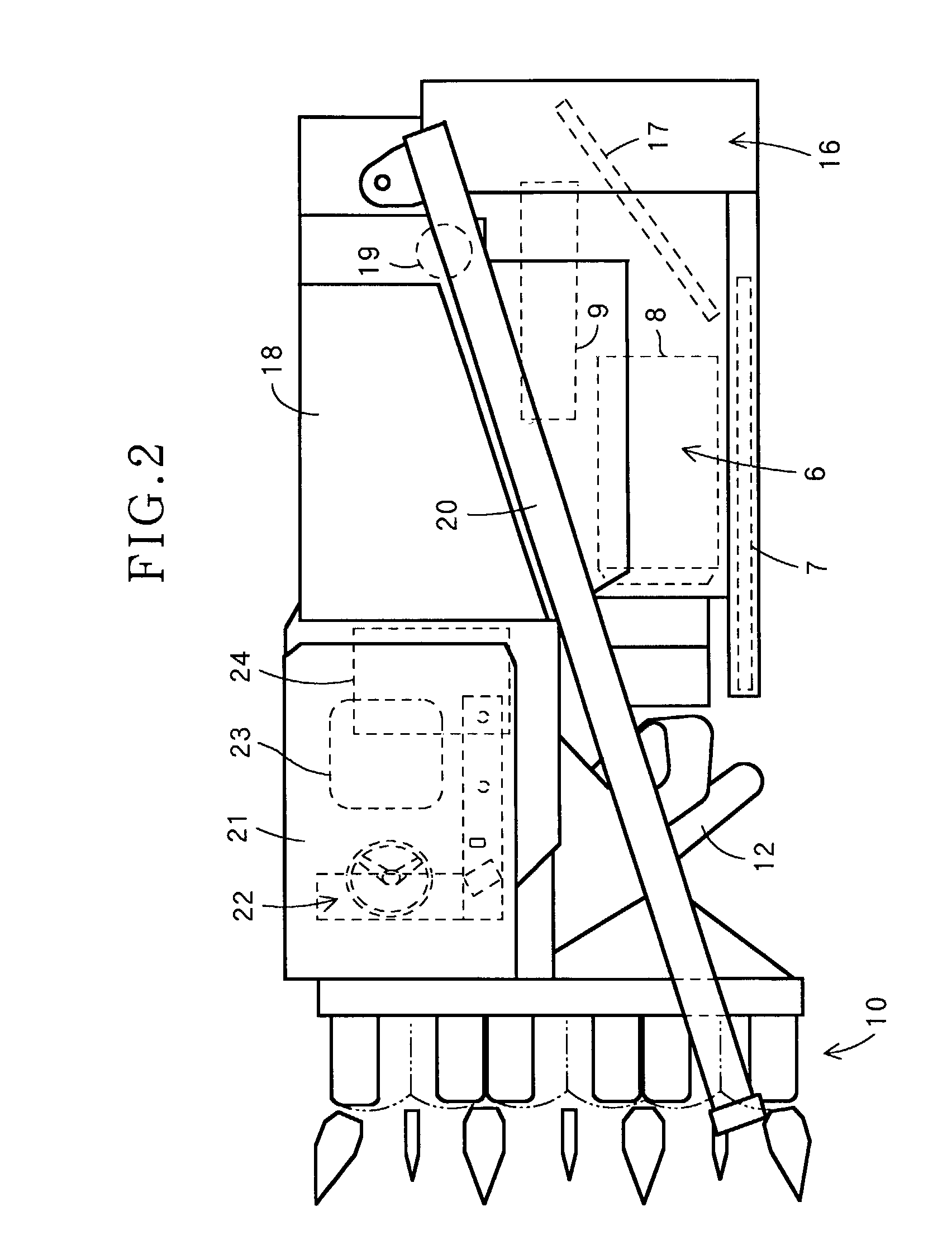
[0049]Now some embodiments of the present invention will be described with reference to the drawings. FIG. 1 is a side view of the combine in its entirety, FIG. 2 a plan view of the same, FIG. 3 a side view of the track frame section, FIG. 4 a partial enlargement view of the same, FIG. 5 is a plan view of the same, and FIG. 6 a partial enlargement view of the same. In the Figures, the reference numerals 1 and 2 denote right and left track frames provided with right and left travel crawlers 3 and 4. The numeral 5 is a platform to be mounted on said track frames 1 and 2, numeral 6 a threshing section for which the left side is provided with the feed chain 7 and in which the handling barrel 8 and the processing barrel 9 are built. Numeral 10 is the reaping section provided with the reaping cutter 11, and the grain stalk conveying mechanism 12. Numeral 13 is the hydraulic reaping elevation cylinder for elevating the reaping section 10 around the reaping fulcrum shaft 15 through the reap...


PUM


Abstract

A mobile agricultural machine, particularly for use as a combine, which demonstrates improved operational movement and travel performance characteristics, and is capable of easily changing direction during operation, includes right and left travel crawlers, supported by drive sprockets and tension rollers, which are installed on right and left track frames through track rollers. Right and left travel frames are capable of being controllably elevated through crawler elevation arms. Tension rollers provide movement to the travel crawlers in a vertical direction, perpendicular to the ground.

Description

FIELD OF THE INVENTION[0001]The present invention relates to a mobile agricultural machine, such as a combine, for continuously reaping and simultaneously threshing grain on a farm.BACKGROUND OF THE INVENTION[0002]In the prior art, as shown in Japanese patent publication number 0128079, the technology includes right and left travel crawlers supported by drive sprockets and tension rollers installed to the right and left track frames through track rollers. The right and left track frames are installed on this machine through crawler elevation arms in a manner where the track frames are movable up and down by correcting the lateral tilt. Said prior art can prevent tension from varying by minimizing changes in the ground contact area of the right and left travel crawlers because, when this machine is elevated, the track frames are lowered in order to come close to the drive sprocket side. There are, however, problems where a shift in the center of gravity of the machine body toward the...

Claims


Application Information

Patent Timeline
Patent Type & Authority Patents(United States)
IPC IPC(8): B62D55/30B62D55/10B62D55/08B62D55/104B62D55/084B62D55/116A01D67/00B62D55/14
CPCB62D55/084B62D55/10B62D55/116B62D55/305
Inventor KIRIHATA, TOSHINORI
Owner YANMAR CO LTD
Why Eureka
Try Eureka