Brake rotor

a brake rotor and rotor body technology, applied in the direction of axially engaging brakes, brake types, braking elements, etc., can solve the problems of radial cracks in the brake rotor, and achieve the effect of reducing the stress of the hoop which is developed in use due to differential thermal expansion of different parts of the brake rotor

Inactive Publication Date: 2005-11-08
MERITOR HEAVY VEHICLE SYST CAMERI
View PDF10 Cites 13 Cited by
  • Summary
  • Abstract
  • Description
  • Claims
  • Application Information

AI Technical Summary

Benefits of technology

[0007]It has been found that by providing recesses between each mounting hole, the hoop stresses which develop in use due to differential thermal expansion of different parts of the brake rotor are reduced. In particular the thermal stresses in that part of the brake rotor immediately radially inside each mounting hole can be reduced to an extent such that cracks no longer form.

Problems solved by technology

However in use, such known brake rotors can develop radial cracks between an inner edge of the mounting holes and the mounting flange central hole.

Method used


Image

  • Brake rotor
  • Brake rotor
  • Brake rotor

Examples


Embodiment Construction

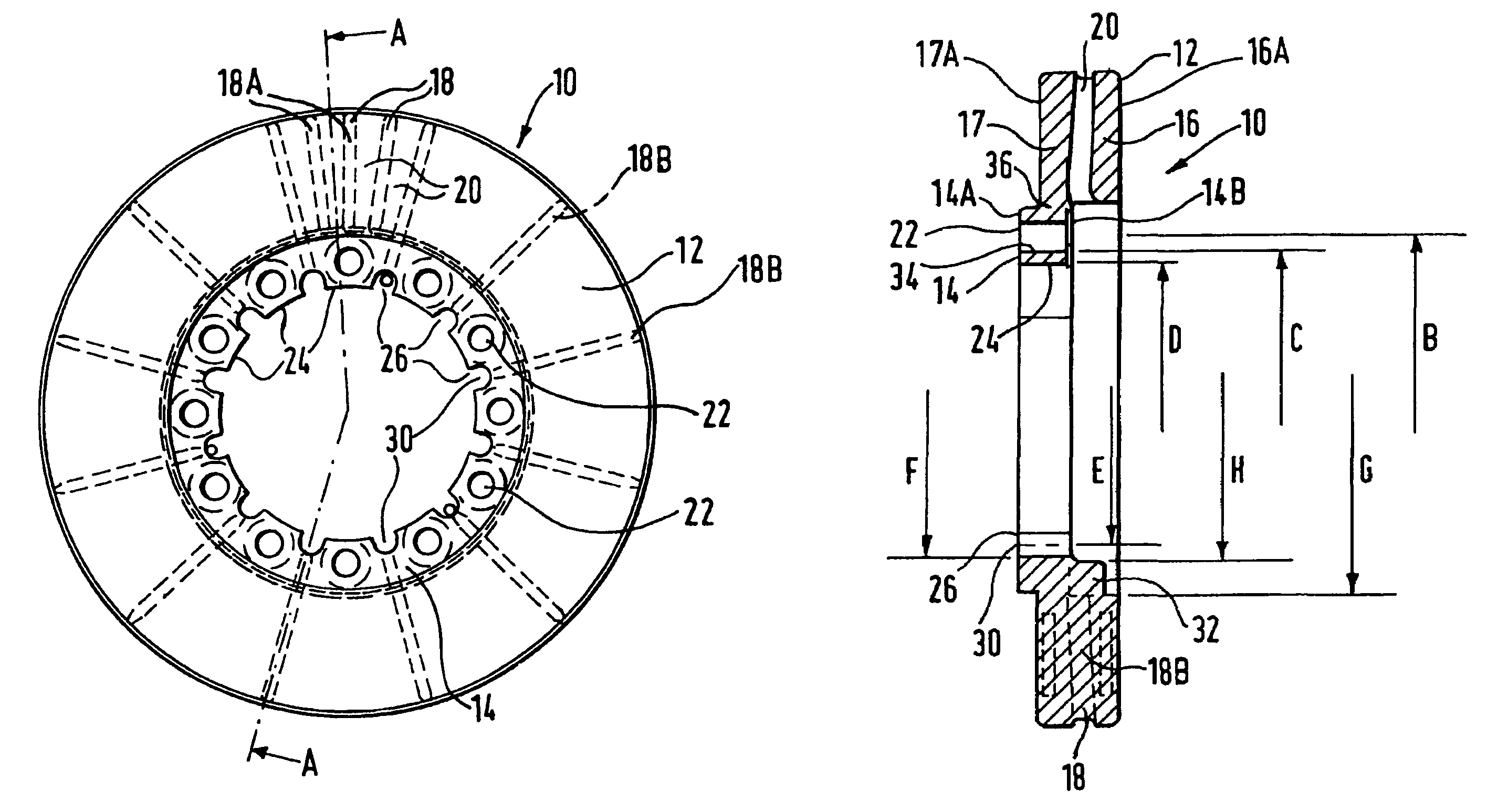
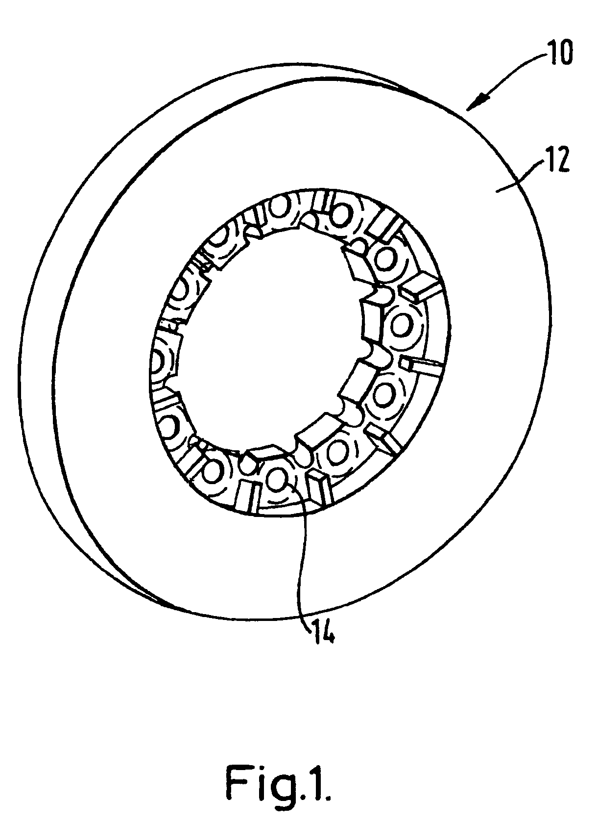
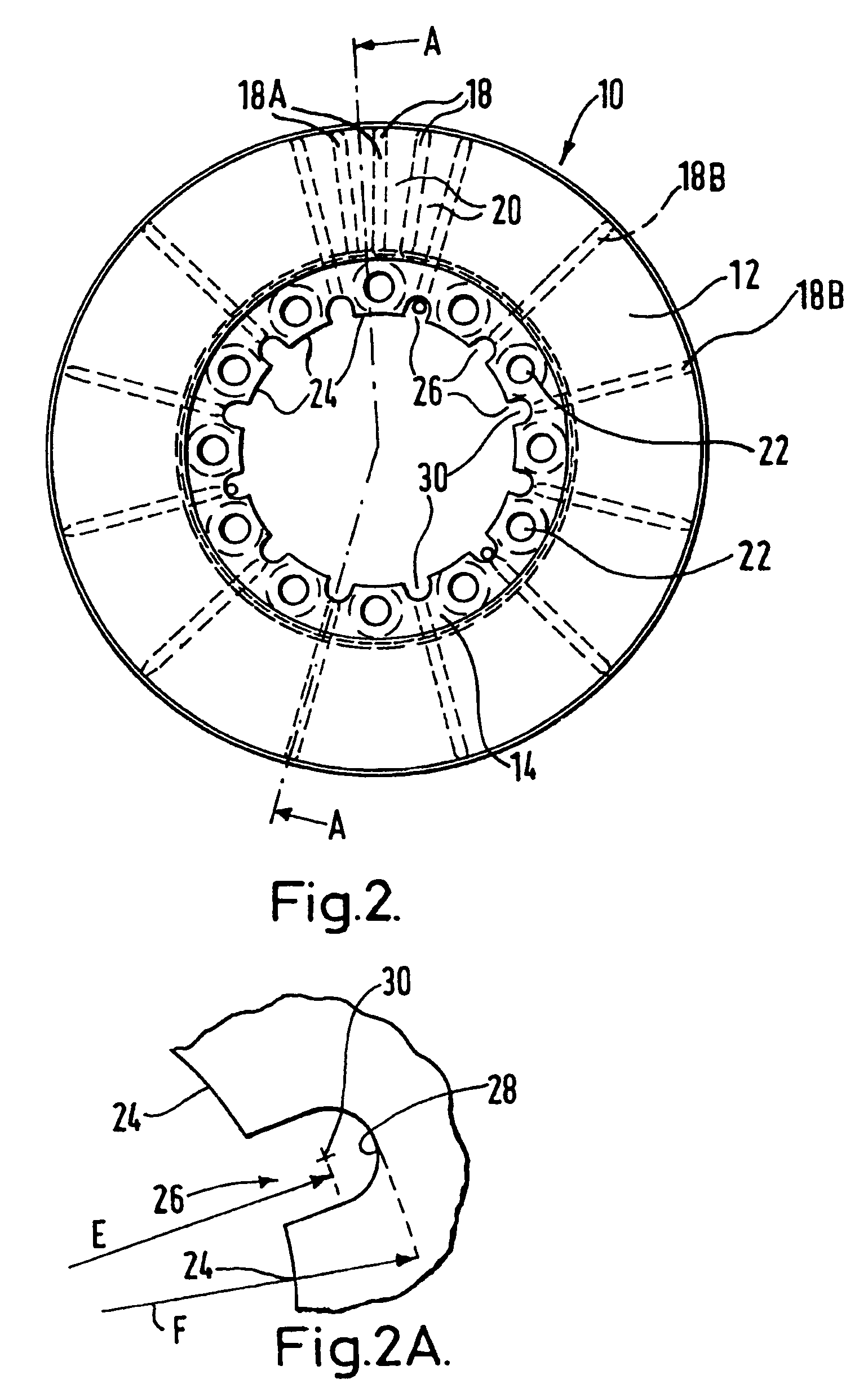
[0013]Specific measurements are used in the description below for illustrative purposes only and are not meant to be limiting in any way. With reference to the figures, there is shown a brake rotor 10 having an annular disc 12 connected to a generally annular mounting flange 14. In particular, it should be noted that the annular disc 12 is connected via an annular region 36. The annular region 36 is a continuous annular region. In this case, the annular region 36 is connected to a brake portion 17.

[0014]The annular disc 12 has brake portions 16 and 17, which are spaced apart by ventilation vanes 18. The brake portions 16 and 17 together with the ventilation vanes 18 define ventilation holes 20. The brake portions 16 and 17 define braking faces 16A and 17A respectively.

[0015]During use, the braking faces 16A and 17A rotate within a recess of a known caliper and are typically mounted on suspension components of a vehicle. Known brake pads are mounted within the caliper and are forced ...


PUM


Abstract

A brake rotor having an annular disc connected to an annular mounting flange, the mounting flange defining a radially inner flange wall and including a plurality of circumferentially spaced mounting holes, in which the flange wall includes a plurality of recesses, with each recess situated circumferentially between adjacent mounting holes in which the brake rotor includes ventilation vanes between opposing braking faces of the annular disc with at least some ventilation vanes including inner vane portions which extend inwardly of a radially inner edge of the annular disc.

Description

REFERENCE TO RELATED APPLICATION[0001]The present invention claims the benefit of United Kingdom (GB) Patent Application Number 0216749.2, filed Jul. 18, 2002.TECHNICAL FIELD[0002]The present invention relates to brake rotors, and in particular to brake rotors for use on vehicles, especially road vehicles, and in particular heavy road vehicles such as trucks and lorries.BACKGROUND OF THE INVENTION[0003]Known brake rotors include a mounting flange having a plurality of circumferentially equally spaced mounting holes. The holes are used to fix the rotor to a wheel hub of the vehicle. The mounting flange includes a circular central hole which fits over various wheel hub components.[0004]However in use, such known brake rotors can develop radial cracks between an inner edge of the mounting holes and the mounting flange central hole.[0005]There is a desire is to produce a brake rotor which is less susceptible to developing such cracks.SUMMARY OF THE INVENTION[0006]Accordingly, the presen...

Claims


Application Information

Patent Timeline
Patent Type & Authority Patents(United States)
IPC IPC(8): F16D65/12
CPCF16D65/123F16D65/128F16D2065/1328
Inventor CONTI, ROBERTO
Owner MERITOR HEAVY VEHICLE SYST CAMERI
Why Eureka
Try Eureka