Fuel pump housing

Inactive Publication Date: 2018-09-06
DELPHI TECH IP LTD
View PDF19 Cites 1 Cited by
  • Summary
  • Abstract
  • Description
  • Claims
  • Application Information

AI Technical Summary

Benefits of technology

[0018]The continuously curved inner surface reduces stresses at the transition between the drilling and the pumping chamber even further.
[0019]For particularly effective reduction of stresses transition between the drilling and the pumping chamber, a boundary between the curved inner surface of the transition region and the spherically-curved inner surface of the pumping chamber may be defined by at least a section of an annulus, each point on the section being a point of inflection of the continuously curved surface. The annular shaping of the opening also advantageously causes hoop stresses in the pumping chamber to be distributed around the circumference of the opening, thereby preventing the stresses from concentrating at any particular point around the perimeter of the transition region.
[0020]The drilling may

Problems solved by technology

The combination of these effects leads unexpectedly to the peak stress in th

Method used


Image

  • Fuel pump housing
  • Fuel pump housing
  • Fuel pump housing

Examples


Embodiment Construction

[0040]References in the following description to “upper”, “lower” and “side”, and other terms having an implied orientation, are not intended to be limiting and refer only to the orientation of the parts shown in the accompanying drawings.

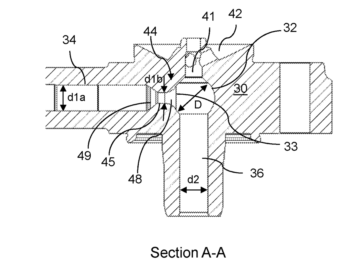
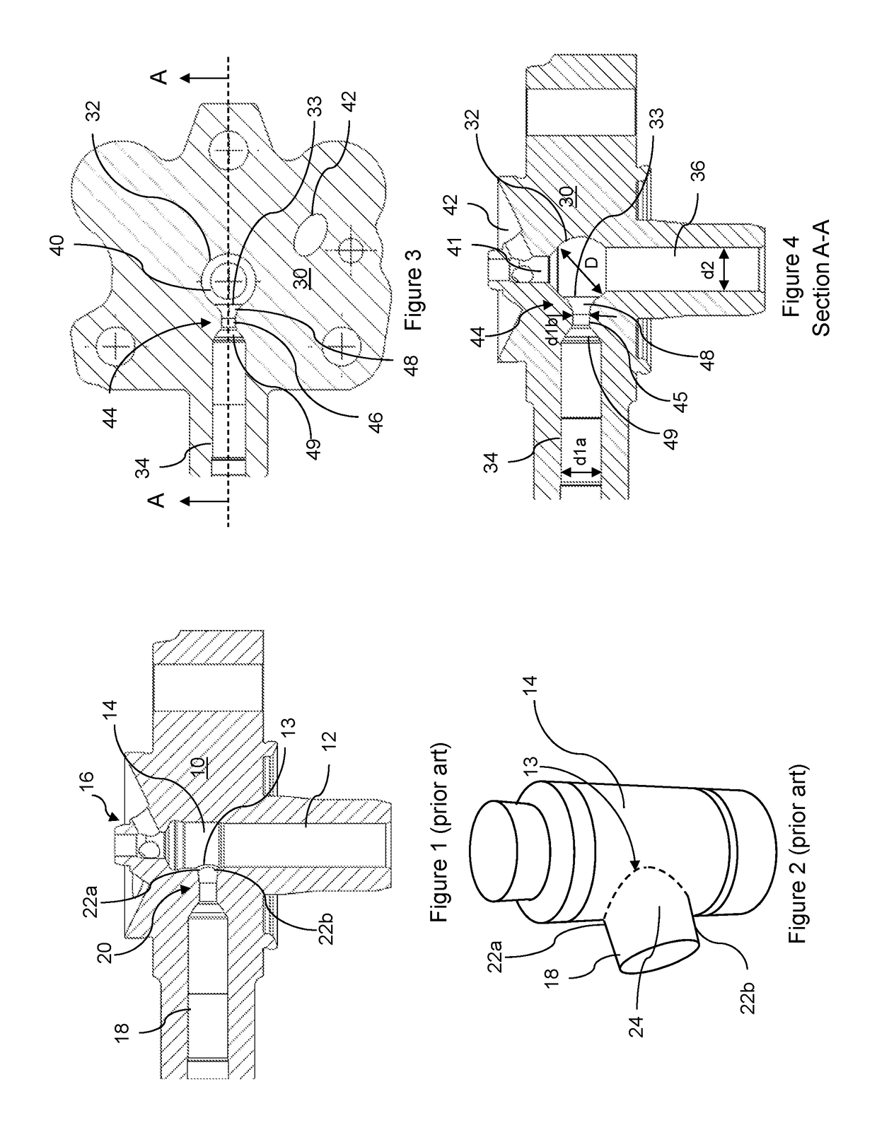
[0041]Referring to FIGS. 3 and 4, a fuel pump for use in a common rail fuel injection system in a diesel engine of a vehicle includes a fuel pump housing 30 in the form of a pump head. The fuel pump housing 30 is provided with a pumping chamber 32 that is intersected by first, second and third drillings 34, 36, 41.

[0042]The first drilling defines an outlet drilling 34 for carrying fuel that has been pressurised within the pumping chamber 32 to a pump outlet (not shown), which further communicates with a downstream common rail fuel injection system (also not shown).

[0043]The second drilling defines a plunger bore 36 for receiving a plunger (not shown) of the pump assembly. The plunger is arranged to reciprocate, in use, within the plunger bore 36 un...


PUM


Abstract

A fuel pump housing includes a pumping chamber that is substantially spherical and a drilling intersecting the pumping chamber at an opening. The drilling transitions into the pumping chamber at a transition region of progressively increasing diameter. The transition region and the spherical pumping chamber are configured such that a peak stress in the fuel pump housing is at a location that is spaced away from the opening.

Description

CROSS REFERENCE TO RELATED APPLICATIONS[0001]This application is a national stage application under 35 USC 371 of PCT Application No. PCT / EP2016 / 070997 having an international filing date of Sep. 6, 2016, which is designated in the United States and which claimed the benefit of GB Patent Application No. 1516152.4 filed on Sep. 11, 2015, the entire disclosures of each are hereby incorporated by reference in their entirety.TECHNICAL FIELD[0002]The invention relates to a fuel pump housing. In particular, the invention relates to a fuel pump housing for use in a common rail fuel injection system of a diesel engine for a vehicle.BACKGROUND TO THE INVENTION[0003]Fuel pump housings typically comprise a pumping chamber that is intersected by passages or drillings. Fuel flows into and out of the pumping chamber via these drillings[0004]FIG. 1 shows part of a known pump assembly for use in a common rail fuel injection system of a diesel engine. The pump assembly includes a fuel pump housing 1...

Claims


Application Information

Patent Timeline
IPC IPC(8): F02M59/44F02M55/02F02M59/02
CPCF02M59/44F02M55/025F02M59/025F02M59/462F04B53/16
Inventor FAIRBAIRN, MATTHEWGARLAND, PAUL FRANCISPEDLEY, TOBY
Owner DELPHI TECH IP LTD
Why Eureka
Try Eureka