Rotary lock seal

a technology of locking seals and shackles, which is applied in the direction of building locks, identification means, constructions, etc., can solve the problems of 008's shanks or shackles being exposed to bolt cutters or other shears, and the task of securing containers against break-ins has proved difficult to solv

Inactive Publication Date: 2005-11-08
SECURUS ENTERPRISES
View PDF13 Cites 23 Cited by
  • Summary
  • Abstract
  • Description
  • Claims
  • Application Information

AI Technical Summary

Benefits of technology

[0011]It is therefore a general object of the present invention to provide

Problems solved by technology

However, the task of securing such containers against break-ins has proven difficult to solve.
Although this apparatus provides protection for the hasp, it still leaves the shank of the security seal/pin open for tampering or cutting, through the openings in the front face.
Similarly, padlock-type security devices such as t

Method used


Image

  • Rotary lock seal
  • Rotary lock seal
  • Rotary lock seal

Examples


Embodiment Construction

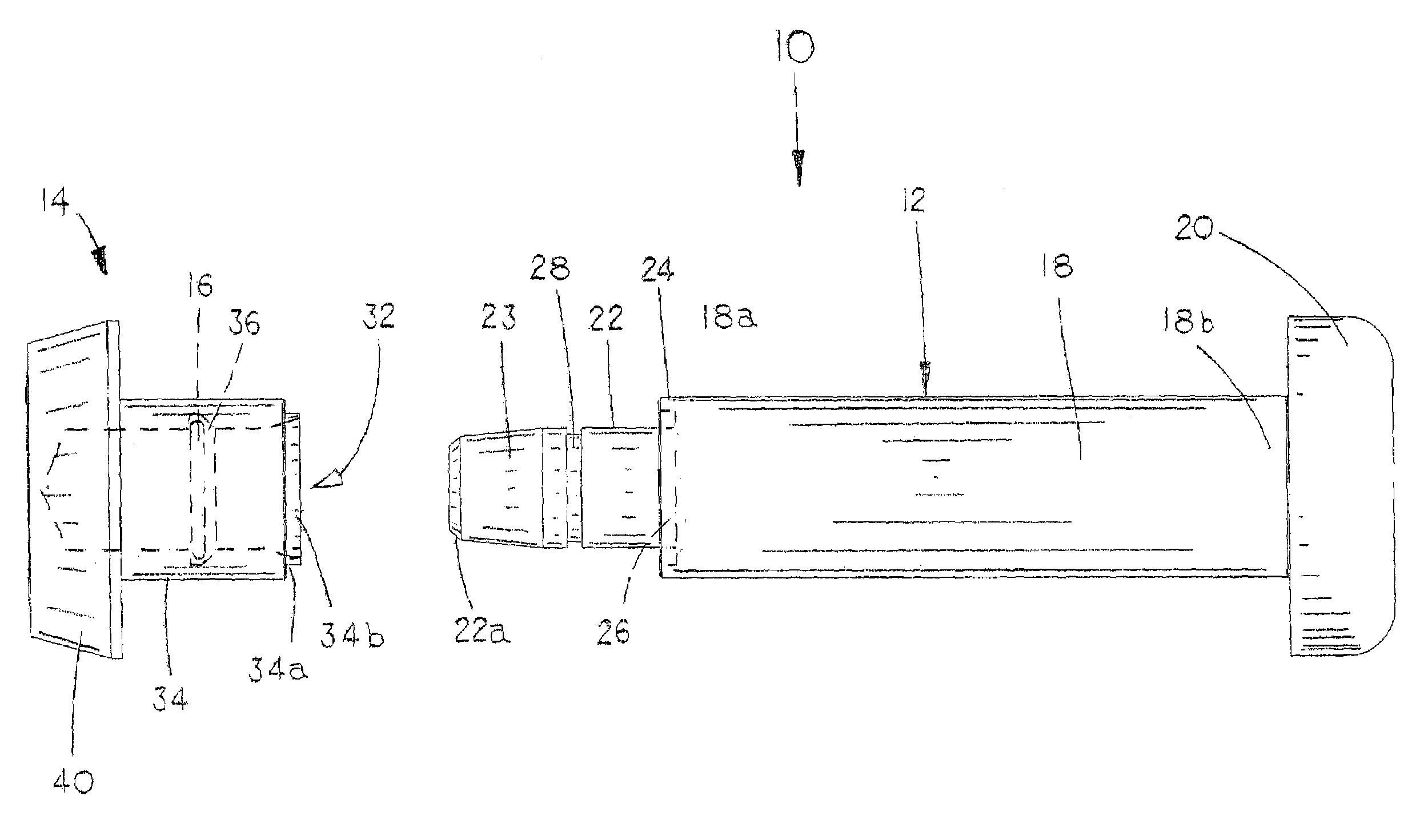
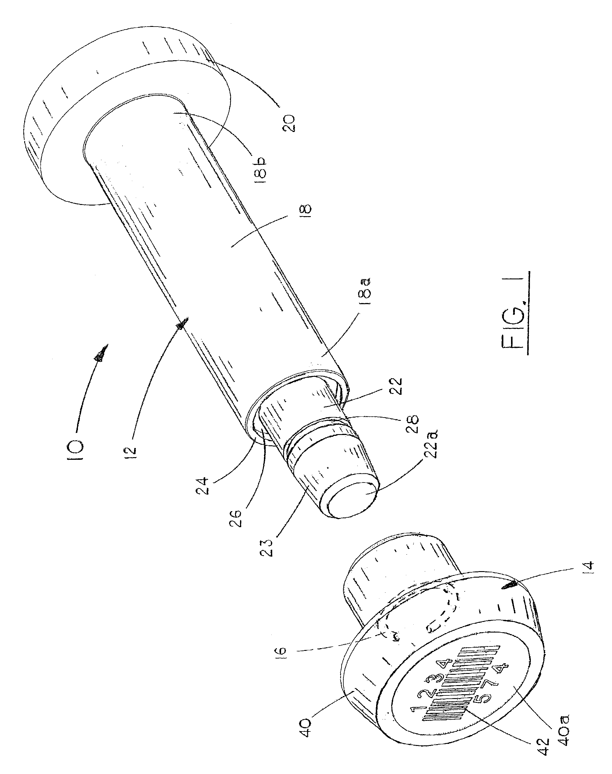
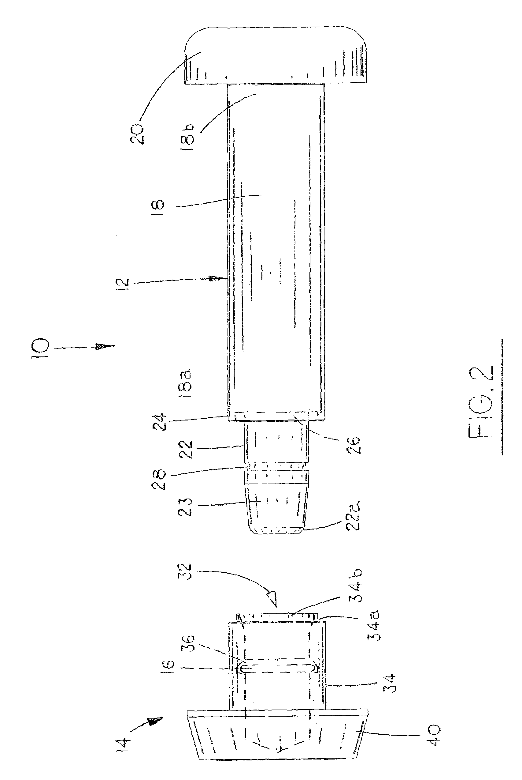
[0019]Referring to the drawings, in which similar or corresponding parts are identified with the same reference numeral, and more particularly to FIGS. 1 and 2, the rotary lock seal of the present invention is designated generally at 10 and includes three major components, namely, a pin 12, a cap 14, and a locking ring 16.

[0020]Seal pin 12 is preferably formed of hardened steel or similar material that is not easily bent, cut or broken. Seal pin 12 includes an elongated solid cylindrical shaft 18 with a forward end 18a and a rearward end 18b. An enlarged head 20 is formed on the rearward end 18b of shaft 18, with a diameter larger than that of shaft 18 to prevent the pin 12 from passing through ears of a latch or other similar lock. The forward end 18a of shaft 18 includes a forwardly projecting peg 22 that is cylindrical in shape and coaxial with shaft 18. Peg 22 has a diameter less than the diameter of shaft 18.

[0021]An annular wall 24, having an outer diameter equal to the diamet...


PUM


Abstract

A rotary lock seal includes a pin with an elongated shaft and an enlarged head at a rearward end. The forward end of the shaft has a peg projecting coaxially therefrom. An end cap has an enlarged head at a forward end and a central bore extending forwardly through the rearward end, forming an annular sidewall. An annular groove on the inner surface of the cap sidewall corresponds with a groove formed on the peg to retain a locking ring within the pair of aligned grooves when the cap is positioned over the peg on the pin. The locking ring prevents removal of the cap once secured on the pin.

Description

CROSS-REFERENCES TO RELATED APPLICATIONS[0001]Applicant claims the benefit of U.S. Provisional Application Ser. No. 60 / 364,203, filed Mar. 14, 2002.STATEMENT AS TO RIGHTS TO INVENTIONS MADE UNDER FEDERALLY SPONSORED RESEARCH AND DEVELOPMENT[0002](Not applicable)BACKGROUND OF THE INVENTION[0003](1) Field of the Invention[0004]The present invention relates generally to apparatus for securing the latch of a shipping container, and more particularly to an improved lock seal on a rotary lock for preventing unauthorized access to a shipping container.[0005](2) Background Information[0006]Shipping containers are widely used in the transportation of various types of goods, both domestically and internationally. However, the task of securing such containers against break-ins has proven difficult to solve.[0007]Prior art attempts include such devices as hasp protectors and various bolt seals. For example, U.S. Pat. No. 5,118,149 discloses a container hasp protector with a metal box with an op...

Claims


Application Information

Patent Timeline
IPC IPC(8): G09F3/03
CPCG09F3/0317G09F3/0364Y10T292/494Y10T292/507Y10T292/51
Inventor PALZKILL, RAYMOND G.FEILMEIER, KEITH R.
Owner SECURUS ENTERPRISES
Why Eureka
Try Eureka