
Implantable medical device including a surface-mount terminal array

a terminal array and medical device technology, applied in the direction of coupling device connection, securing/insulating coupling contact member, therapy, etc., can solve the problems of limiting design freedom, increasing costs, and reducing yield

Active Publication Date: 2005-11-08
MEDTRONIC INC
View PDF17 Cites 70 Cited by
  • Summary
  • Abstract
  • Description
  • Claims
  • Application Information

AI Technical Summary

Benefits of technology

[0007]According to a first aspect of the invention there is provided an implantable medical device which comprises an enclosure, a first plurality of electrical contacts disposed within the enclosure, at least a first electrical component secured within the enclosure, a second plurality of electrical contacts on the first electrical component, and a terminal array for providing electrical coupling between the first and second plurality of electrical contacts. The terminal array comprises a housing having a plurality of apertures therethrough, the housing having a first side and a second opposite side. Each of a plurality of conductive terminals is positioned within one of the plurality of apertures and has a first contact region proximate the first side of the housing and a second contact region proximate the second side of the housing. The first contact region is electrically coupled to one of the first plurality of electrical contacts, and the second contact region is electrically coupled to one of the second plurality of contacts.

Problems solved by technology

The construction of such implantable medical devices using the above described basic architecture oftentimes requires complex manufacturing operations which increase costs, lower yields, and limit design freedom.
That is, the substrates are not directly compatible with welding or wire-bonding.
In the case of welding the substrate metalization and even the substrate itself may be damaged due to their respective low melting points.
Ceramic substrates may also be damaged by the rapid local heating.
Furthermore, the use of a gold finish can cause brittle solder joints.
Unfortunately, this presents certain problems.
First, components can “swim” or “float” on solder pads during the soldering process resulting in non-uniform component spacing and excessive tilting with respect to the PWB surface.
Additionally, as the size of the individual terminals or contacts continues to shrink, the terminals are difficult to manage with current pick-and-place surface-mount assembly equipment.
These approaches, however, still suffer from the above described disadvantages.
Unfortunately, the impedance through each terminal from one surface to the other surface results in large voltage drops at high currents.

Method used


Image

  • Implantable medical device including a surface-mount terminal array
  • Implantable medical device including a surface-mount terminal array
  • Implantable medical device including a surface-mount terminal array

Examples


Embodiment Construction

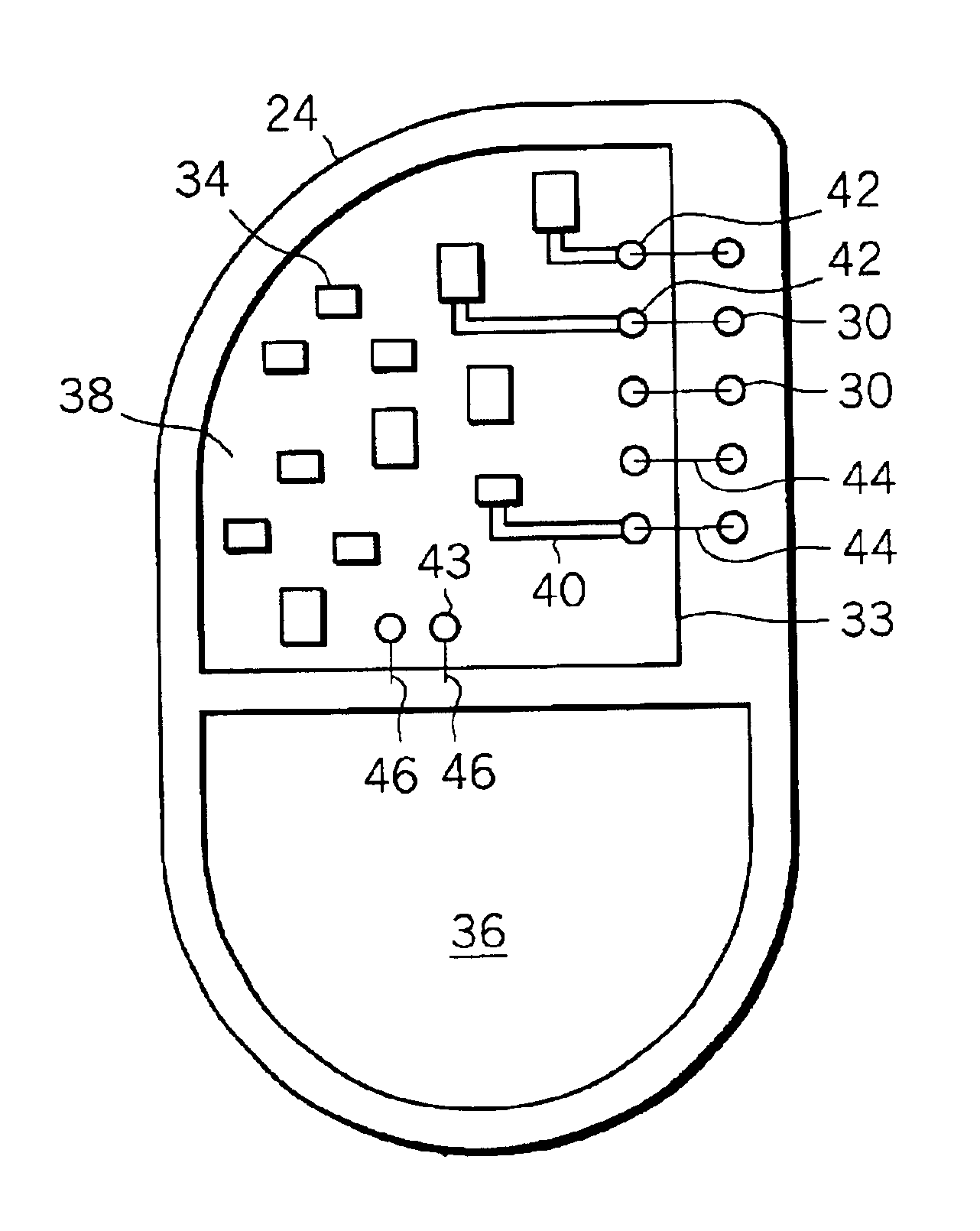
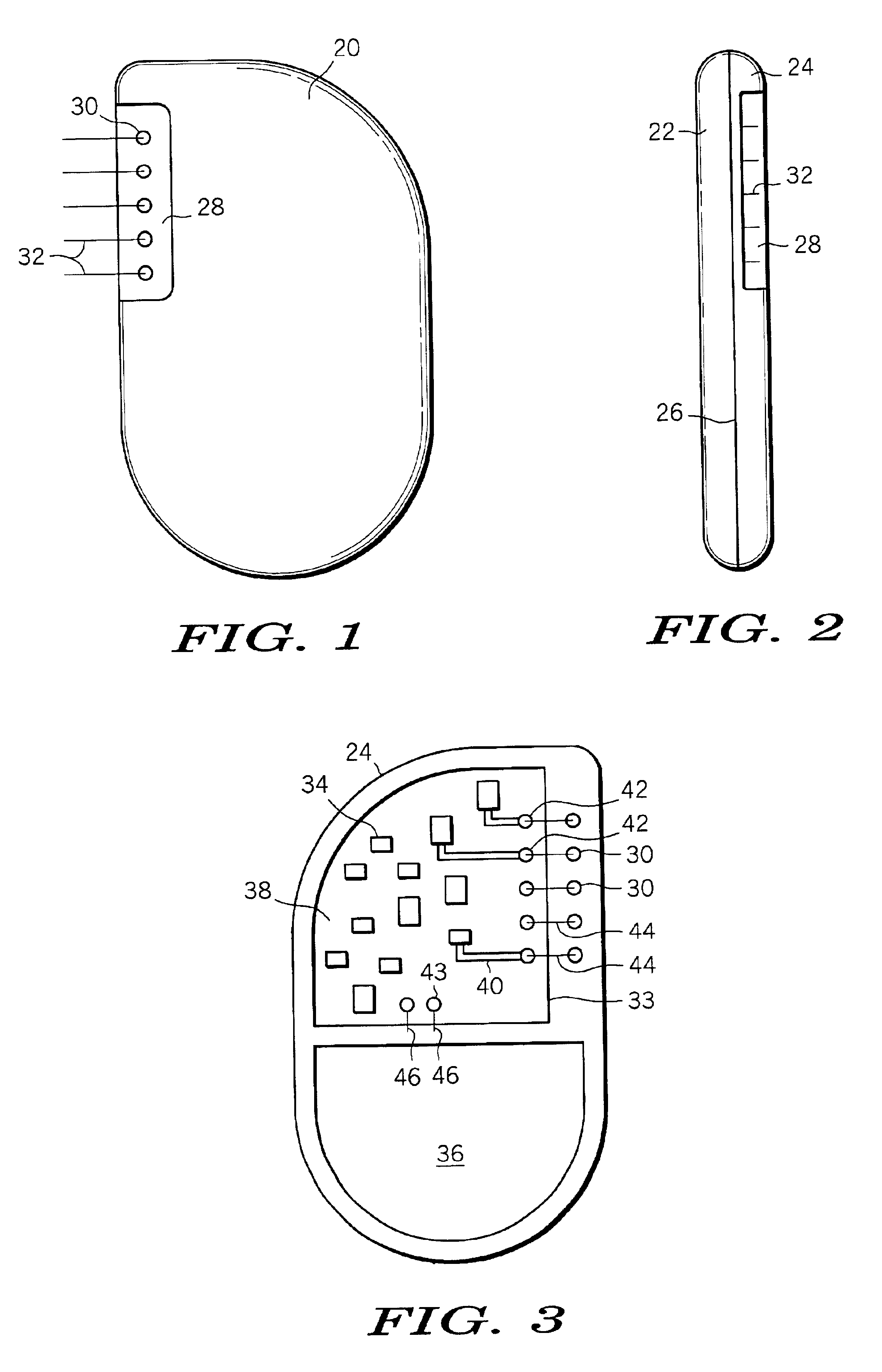
[0018]FIG. 1 and FIG. 2 are plan and side views respectively of an implantable medical device in accordance with the present invention. As can be seen, the implantable medical device comprises an enclosure 20 made, for example, of titanium or other suitable biocompatible metal. Enclosure 20 includes first and second halves 22 and 24 respectively which are joined, as for example by welding, along seem 26 to provide a hermetically sealed enclosure which prevents fluid access to the electrical components (e.g. battery, circuitry, etc.) housed within. Enclosure 20 is provided with a recessed area 28 which is equipped with a plurality of feed-throughs 30 from which extend a plurality of leads or feed-through wires 32. Leads 32 are in turn electrically connected via a connecter plug (not shown) to other lead wires which are deployed in an organ which is to be monitored and / or impacted by the implantable medical device. For example, the leads associated with a pacemaker or defibrillator wo...


PUM


Abstract

An implantable medical device comprises an enclosure, a first plurality of electrical contacts disposed within the enclosure, at least a first electrical component secured within the enclosure, a second plurality of electrical contacts on the first electrical component, and a terminal array for providing electrical coupling between the first and second plurality of electrical contacts. The terminal array comprises a housing having a plurality of apertures therethrough, the housing having a first side and a second opposite side. Each of a plurality of conductive terminals is positioned within one of the plurality of apertures and has a first contact region proximate the first side of the housing and a second contact region proximate the second side of the housing. The first contact region is electrically coupled to one of the first plurality of electrical contacts, and the second contact region is electrically coupled to one of the second plurality of contacts.

Description

FIELD OF THE INVENTION[0001]This invention relates generally to implantable medical devices, and more particularly to an implantable medical device incorporating a surface-mount solderable terminal array including surfaces suitable for welding and / or wire-bonding.BACKGROUND OF THE INVENTION[0002]Implantable medical devices such as pacemakers, defibrillators, neuro-stimulators, and the like are generally deployed in a housing comprising two metal halves forming a “clam shellassembly. Electrical communication to external sensing electrodes and / or therapy delivery electrodes is often accomplished by means of a rigid plastic connecting module fixed to an outer portion of the housing. One or more feed-through connectors permit electrical communication to and from the electrical components or circuitry contained within the housing while at the same time maintaining the hermeticity of the device.[0003]The construction of such implantable medical devices using the above described basic ar...

Claims


Application Information

Patent Timeline
Patent Type & Authority Patents(United States)
IPC IPC(8): A61N1/372A61N1/375
CPCA61N1/3754
Inventor RUBEN, DAVID A.RIES, ANDREW J.MILLA, JUAN G.ROLES, RANDY S.BRUNEAU, TERRY W.WARREN, STEVE CRAIGPARKIN, DAVID W.ANDERSON, II, JOHN V.DAY, JOHN K.HEMANN, JR., ROBERT V.
Owner MEDTRONIC INC
Features
  • Generate Ideas
  • Intellectual Property
  • Life Sciences
  • Materials
  • Tech Scout
  • Unparalleled Data Quality
  • Higher Quality Content
  • 60% Fewer Hallucinations
Learn More