Optical disk device

a technology of optical disk and clamping mechanism, which is applied in the direction of magnetic recording, data recording, instruments, etc., can solve the problems of increased load on the motor, large force, and difficulty in making the optical disk thin, and achieve the effect of smooth clamping and releasing the optical disk

Inactive Publication Date: 2005-11-08
TEAC CORP
View PDF11 Cites 5 Cited by
  • Summary
  • Abstract
  • Description
  • Claims
  • Application Information

AI Technical Summary

Benefits of technology

[0008]The present invention aims to provide a thin device which is able to smoothly carry out operations of clamping and releasing an optical disk.

Problems solved by technology

However, such a constitution has a problem that it is difficult to make the optical disk device thin because it is necessary to arrange the damper above the turntable.
Also, a large force is required when clamping of the optical disk is released because clamping is performed by magnetic force, which means that the load on a motor increases.

Method used


Image

  • Optical disk device
  • Optical disk device
  • Optical disk device

Examples


Embodiment Construction

[0053]An embodiment of the present invention will now be described based on the accompanying drawings.

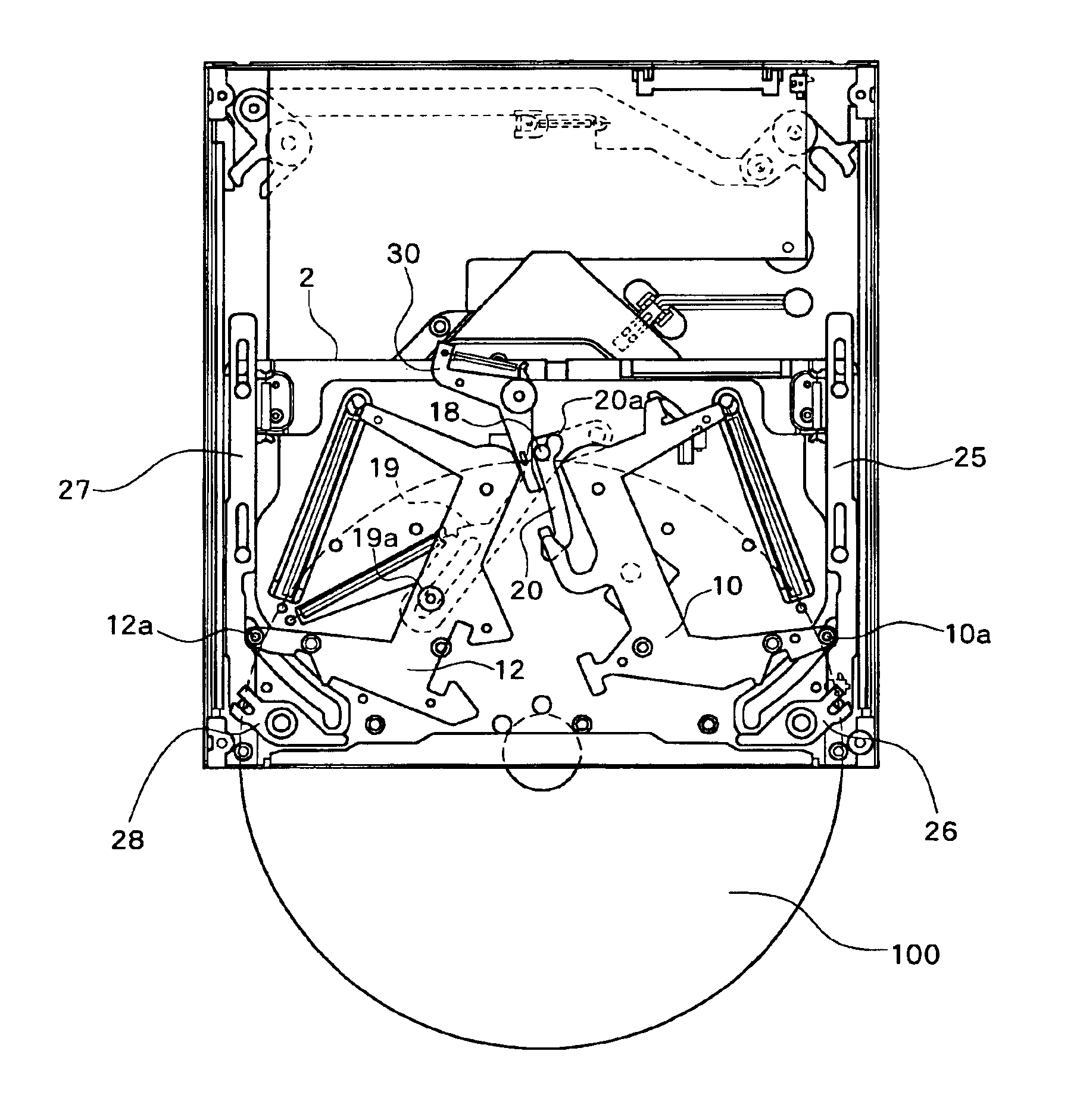
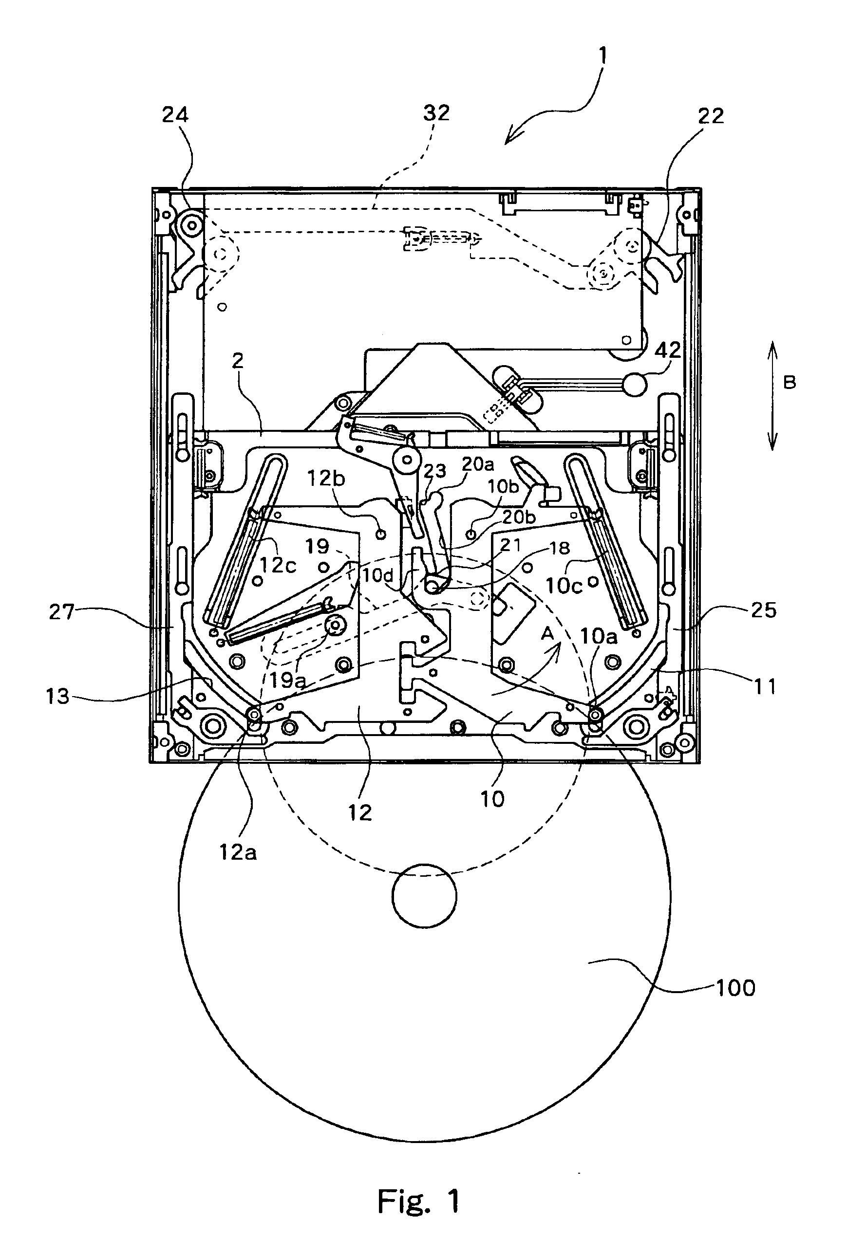
[0054]FIG. 1 shows the constitution of an optical disk device according to this embodiment. An optical disk device 1 has an opening section at its front section and a user inserts an optical disk 100 through the opening section. A pair of arms 10 and 12 are installed at a carrier section 2 of the optical disk device 1, and pins 10a and 12a are installed at ends of the arms 10 and 12, respectively.

[0055]The arm 10 is connected with the carrier section 2 via an axis 10b which is inserted into the carrier section 2 leaving a space between the axis 10b and the carrier section 2. The arm 10 can rotate and move with the axis 10b as a center within a plane above the carrier section 2. The axis 10b is arranged in an opening (hole), which is formed at the carrier section 2, in a state leaving a space between the axis 10b and the opening, whereby a position of the arm is defined in a rough ma...


PUM

PropertyMeasurementUnit
angleaaaaaaaaaa
diameteraaaaaaaaaa
diameteraaaaaaaaaa

Abstract

There is provided a thin optical disk device having a slot-in mechanism which is able to smoothly carry out operations of clamping and releasing an optical disk, including an optical pickup which carries out reading and/or writing from/to the optical disk, a turntable which places the optical disk at an operating position of the optical pickup and rotates the optical disk, a clamper which is arranged at an approximate center of the turntable and can freely advance and retreat in a direction of a diameter of the optical disk, and a device for clamping an inside diameter section of the optical disk at a location directly above the clamper with the optical disk being held by sandwiching the optical disk and for pressing the inside diameter section from the side of a non-writing surface of the optical disk and clamping the inside diameter section to the clamper.

Description

BACKGROUND OF THE INVENTION[0001]1. Field of the Invention[0002]The present invention relates to an optical disk device, and particularly to a clamp mechanism of an optical disk.[0003]2. Description of the Related Art[0004]Heretofore, an optical disk device which drives an optical disk, such as a CD, a CD-ROM, or a DVD has adopted a slot-in mechanism in which when the optical disk is inserted through a disk insertion opening, the optical disk is carried to a write or read position by means of a carrier mechanism.[0005]In this slot-in mechanism, after the optical disk is carried to a prescribed position, a turntable rises and the optical disk is placed on the turntable. After that, the turntable rises further and a clamper which has been waiting above the turntable sticks to the turntable due to magnetic force of a magnet in the turntable. As a result, the optical disk can be sandwiched between the turntable and the clamper.[0006]However, such a constitution has a problem that it is ...

Claims


Application Information

Patent Timeline
Patent Type & Authority Patents(United States)
IPC IPC(8): G11B17/04G11B17/028G11B17/051
CPCG11B17/0284G11B17/0288G11B17/0515
Inventor FUJIMURA, NOBUHIKO
Owner TEAC CORP
Why Eureka
Try Eureka