Log rocker

a technology of log rocker and rocker body, which is applied in the field of log rocker, can solve the problems of not providing enough height, leverage, clearance, or adjustability to be suitable for many common logging operations, and not allowing a workman to position the log rocker device entirely under the log

Inactive Publication Date: 2005-11-15
RADCLIFF JOHN B
View PDF12 Cites 13 Cited by
  • Summary
  • Abstract
  • Description
  • Claims
  • Application Information

AI Technical Summary

Benefits of technology

[0007]A log rocker device is presented having an elongated handle approximately six feet long. Attached at the lower back end of the handle is a cylindrical fulcrum strong enough to enable the workman to rotate a large, heavy log from the ground. Also attached to the bottom part of the elongated handle is a pair of pointed, semi-circular prongs. The lower prongs are able to slide underneath a log even when it is sunken into the ground. At the upper end of the circular prongs is a pivotable upper surround member. This pivotable surround member is also semi-circular and is designed to pivot over and around the log to be raised. A spike at the end of the semi-circular surround member is driven into the log. The entire device thus surrounds the log for lifting. By pulling down on the upper handle attached to the elongated lever arm, the device pivots on the lower cylindrical fulcrum and allows the log to be lifted approximately six to twelve inches off of the ground. Because of the semi-circular nature of the surrounding arms and the large cylindrical fulcrum, lifting a log up off the ground is made much easier and efficient.

Problems solved by technology

A chainsaw is quickly dulled and put out of use when it is utilized to cut dirt or rock.
While Feighery is an improvement in the log-cutting field, it does not provide enough height, leverage, clearance, or adjustability to be suitable for many common logging operations.
However, one drawback of the Weisgerber device is that it does not allow a workman to position the log rocker device entirely under the log.
Also, many commonly felled logs would be too large in diameter to be lifted by the Weisgerber device.
Many devices such as that found in Weisgerber and Feighery are not capable of lifting a log that has been sunken into the ground.

Method used


Image

  • Log rocker
  • Log rocker
  • Log rocker

Examples


Embodiment Construction

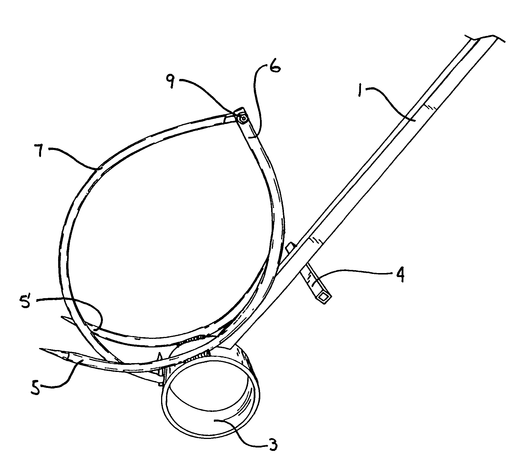
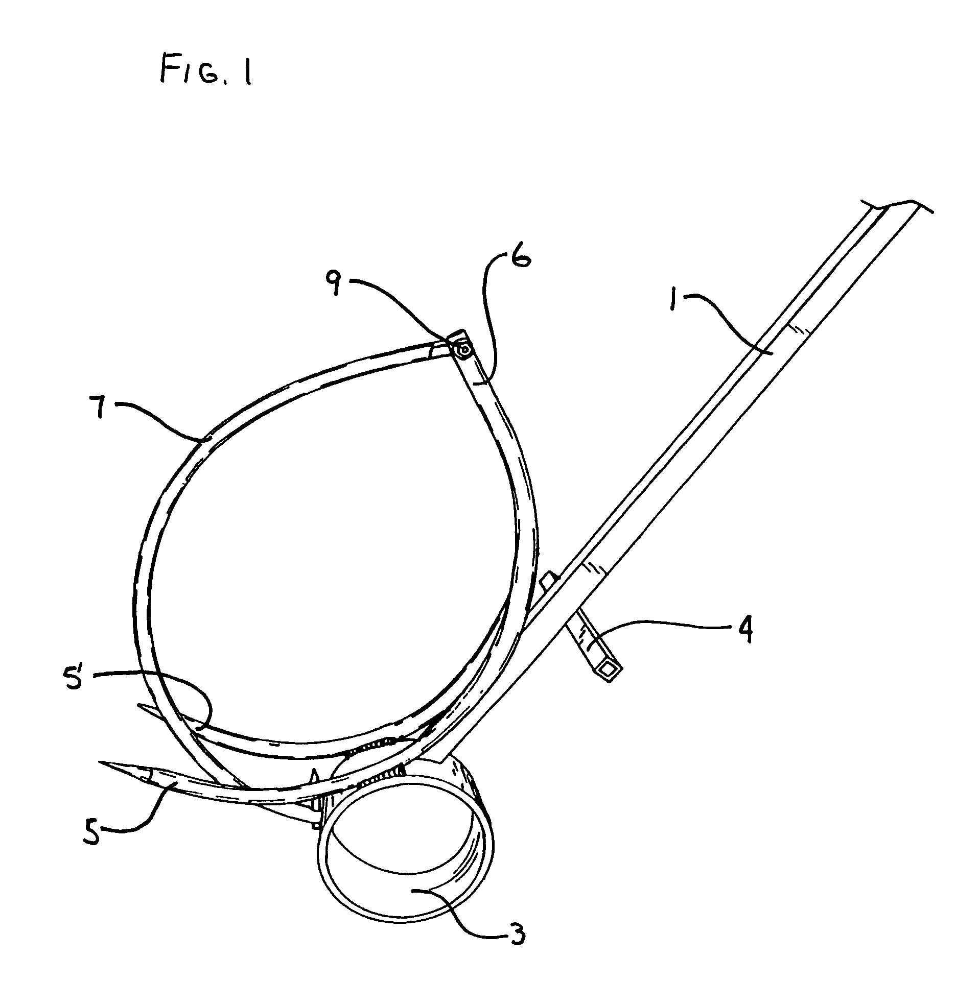
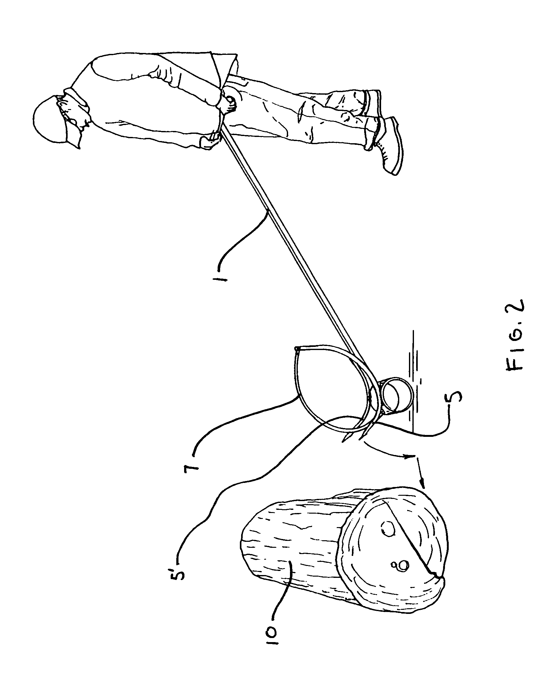
[0011]A strong yet lightweight log rocker enables a workman to lift a log from the ground. The log rocker comprises an elongated lever arm 1 which may have a square cross section as shown. However, the lever arm may also have a circular cross section while still keeping within the spirit and disclosure of this invention. a main feature of the elongated lever arm 1 is that it be made of a strong metal such as steel. Attached to the top of the elongated lever arm 1 is a perpendicular handle 2, as best shown in FIG. 3.

[0012]At the bottom and back of the lever arm 1 is a lower, back fulcrum cylinder 3. This fulcrum cylinder 3 is preferably made of strong tubular steel as best shown in drawing FIG. 1. The fulcrum 3 must be strong enough to carry the weight of a large log, such as shown at 10. Also attached to the lever arm 1 is a lower, intermediate perpendicular foot brace 4. This foot brace allows the logger to use the upper handle 2 with his hands and the foot brace 4 with one foot in...


PUM


Abstract

A log rocker has a long lever arm with a back cylinder fulcrum at its bottom end. Also attached to the bottom end of the lever arm is a semi-circular, curved, pair of prongs and an upper, semi-circular shaped, pivoting surround arm. The surround arm has a spike at its outer end. The lever arm also has a handle at the top and a foot brace about one-third from the ground. To use the device the logger forces the pair of prongs underneath a log and then locks the log onto the rocker by rotating the upper, surround, pivot arm and driving the spike into the log to secure the device around the log. The lever can then be rotated to allow the logger to raise the log up off the ground and onto the cylindrical fulcrum for cutting.

Description

BACKGROUND OF THE INVENTION[0001]This invention relates to the field of logging and converting logs into firewood with a chainsaw. More particularly, a device is presented which lifts a log from the ground so that a chainsaw may cut the log into smaller cylindrical pieces.[0002]In the logging and tree-cutting field, chainsaws have been utilized in order to cut down trees. Once the trees are horizontally on the ground, the limbs are normally trimmed with a chainsaw. The tree is then cut into approximately two to three foot cylindrical sections for splitting. Since the circular tree is normally lying partially in the ground after falling, the last part of the longitudinal cut of the log requires that the chainsaw come into contact with the dirt, rocks, or other debris in the ground. A chainsaw is quickly dulled and put out of use when it is utilized to cut dirt or rock. In order to prolong the life of the chainsaw and the efficiency of the workmen, it would is desirable to lift the lo...

Claims


Application Information

Patent Timeline
Patent Type & Authority Patents(United States)
IPC IPC(8): B65G7/00B65G7/08B27B21/00B65G7/02B66F15/00
CPCB27B21/00B65G7/02B66F15/00B65G2201/0282
Inventor RADCLIFF, JOHN B.
Owner RADCLIFF JOHN B
Why Eureka
Try Eureka