
Scanning unit for an optical position measuring device

Inactive Publication Date: 2005-11-15
DR JOHANNES HEIDENHAIN GMBH
View PDF22 Cites 3 Cited by
  • Summary
  • Abstract
  • Description
  • Claims
  • Application Information

AI Technical Summary

Benefits of technology

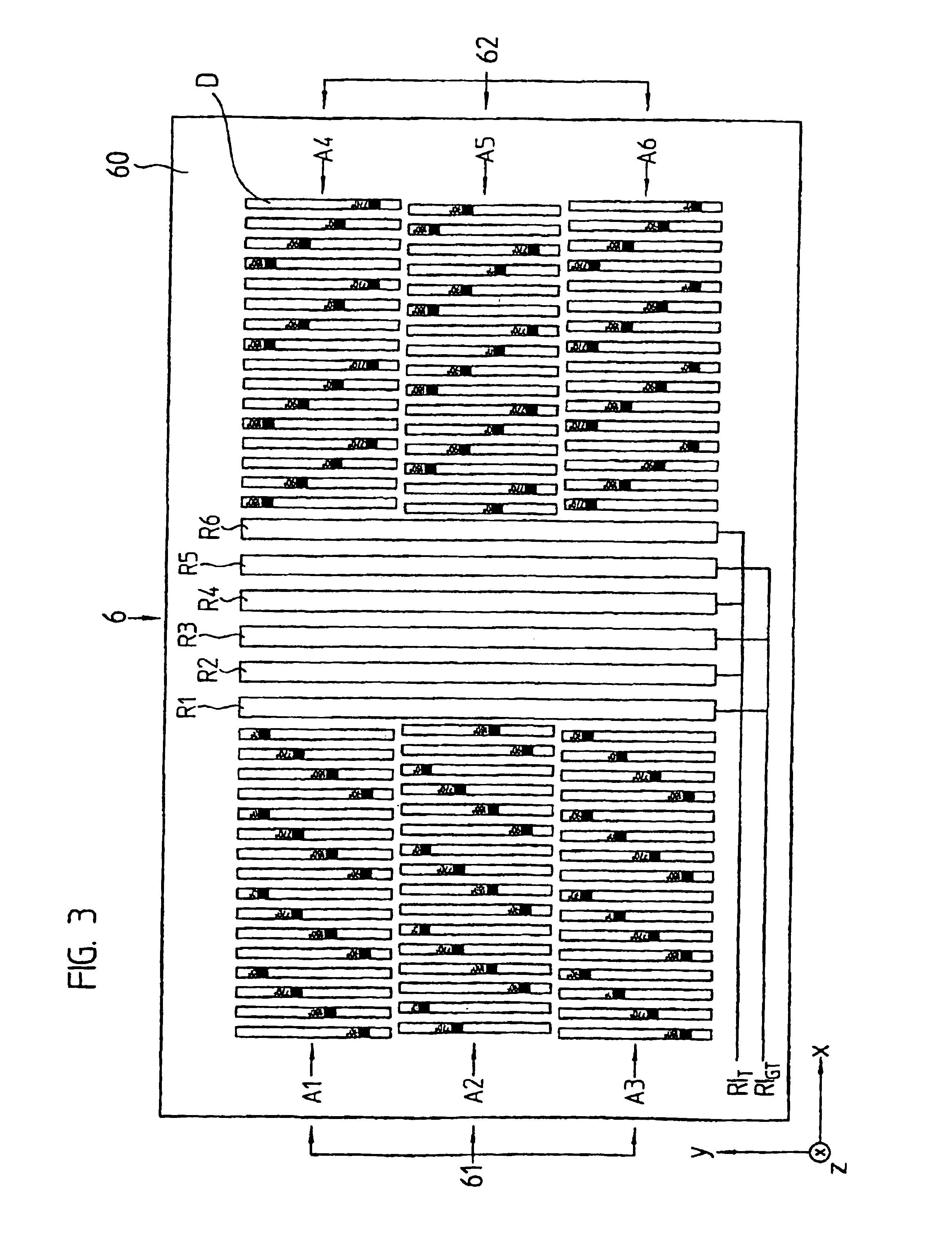
[0008]The scanning unit in accordance with the present invention now assures that even possible short-period interferences with the scanned measuring graduation affect the generation of periodic incremental signals and their further processing in a less erroneous way. Because of the embodiment of the scanning units in accordance with the present invention, so-called single field scanning is assured, wherein the various phase-shifted incremental scanning signals are obtained from a single period of the scanned strip pattern. A uniform effect is achieved for all signals, even in case of a short-period interference.
[0009]Because of the reduced sensitivity to short-period interferences, the scanning units in accordance with the present invention are particularly suitable for position measuring devices having a reference marking which is integrated into the measuring graduation. However, the present invention can basically also be employed in connection with systems which do not provide such a generation of a reference pulse signal.
[0010]The present invention of course is advantageous even in case of intensive soiling of the measuring graduation, and in this case assures an extensively uniform effect on all phase-shifted scanning signals.

Problems solved by technology

The lack of individual partial areas of the measuring graduation has the result that at this location only one of the generated phase-shifted incremental scanning signals is entirely or partially lost, for example the 0° scanning signal.
In this case errors result in the course of further processing of the incremental scanning signals, for example of the signal interpolation.

Method used


Image

  • Scanning unit for an optical position measuring device
  • Scanning unit for an optical position measuring device
  • Scanning unit for an optical position measuring device

Examples


Embodiment Construction

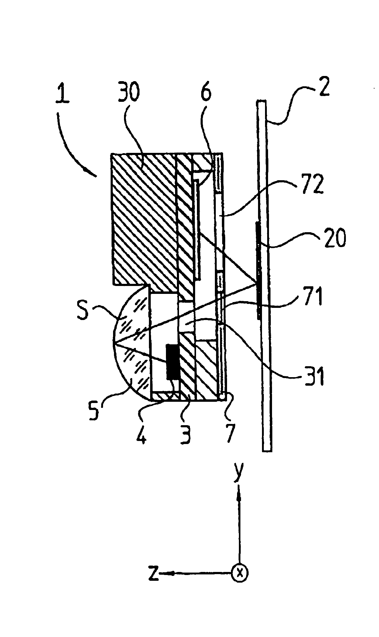
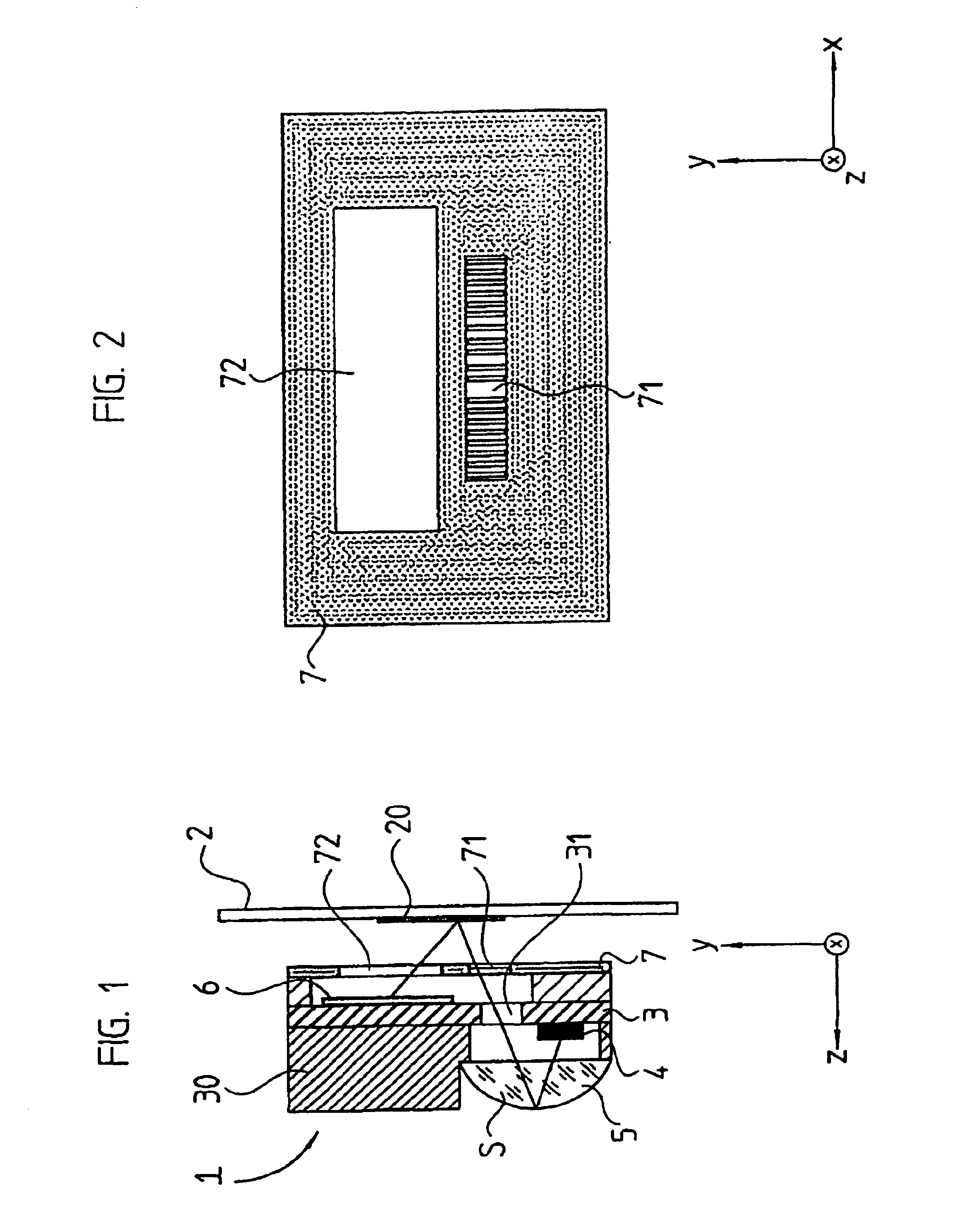
[0021]The scanning beam path of a first optical position measuring device is represented in FIG. 1, wherein a first variant of the scanning unit of the present invention is employed. The first example of an incident light position measuring device represented in FIG. 1 includes a scale 2, as well as a scanning unit 1, which can be moved in relation to the scale 2 in the measuring direction x. The measuring direction x is oriented vertically with respect to the drawing plane.

[0022]A known incremental measuring graduation 20 is provided on the part of the scale 2, which extends in the measuring direction x and includes a periodic sequence of reflective and non-reflective partial areas. A reference marking is integrated into the measuring graduation at one or several defined locations, such as the one described in the already mentioned WO 99 / 08074. An absolute relationship can be provided in a known manner in the course of the position measurement by scanning the reference marking and ...


PUM


Abstract

A scanning unit for an optical position measuring device for scanning a periodic strip pattern in a detector plane, the scanning unit including a detector arrangement including a first detector array with a first set of several radiation-sensitive detector elements, which are arranged next to each other in a first direction on a common support substrate and a second detector array including a second set of several radiation-sensitive detector elements arranged adjacent to the first detector array in a second direction perpendicular with respect to the first direction a detection plane. The second set of several radiation-sensitive detector elements are arranged next to each other in the first direction with a common period PDET, and have a geometrically defined offset (Δx1i) in the first direction with respect to the first set of several radiation-sensitive detector elements.

Description

[0001]The present invention relates to a scanning unit for an optical position measuring device.DESCRIPTION OF THE RELATED ART[0002]Customarily, known optical position measuring devices include a scale with a measuring graduation, as well as a scanning unit which is movable in relation to the latter. In case of a relative movement, a periodic modulation of a strip pattern results in a detection plane, which is detected by a suitable arrangement of electro-optical detector elements for generating incremental signals, and is evaluated for determining the relative positions of the scale and the scanning unit. Several phase-shifted incremental scanning signals are customarily generated for the position determination, wherein the phase shift is 90° as a rule. A so-called reference pulse signal is often additionally generated from the scanning of a reference marker for the precise determination of the absolute position, and is taken into account together with the information regarding the...

Claims


Application Information

Patent Timeline
IPC IPC(8): G01D5/36G01D5/26
CPCG01D5/366
Inventor MAYER, ELMAR J.HOLZAPFEL, WOLFGANG
Owner DR JOHANNES HEIDENHAIN GMBH
Learn More