
Wheel localizer, wheel localization device, system, method and computer program for locating a position of a wheel

a technology of localization device and positioner, which is applied in the direction of vehicle components, tyre measurements, instruments, etc., can solve the problems of uneconomic approach, difficult distinction between signals from the left and right, and extensive concepts, etc., and achieves the effect of more cost-effective and better suitabl

Active Publication Date: 2019-01-24
INFINEON TECH AG
View PDF3 Cites 0 Cited by
  • Summary
  • Abstract
  • Description
  • Claims
  • Application Information

AI Technical Summary

Benefits of technology

The patent describes a system that can automatically determine the positions of wheels on a vehicle based on information related to their expected rotational frequencies. This information can be obtained from sensors or through an analysis of the vehicle's movement. The system can be retro-fitted to existing sensors and is independent from other systems such as ABS, making it more cost-effective. Additionally, it avoids the need for a standardized interface and is better suited for after-market implementations. The technical effects of this system include improved accuracy and efficiency in determining wheel position, as well as greater flexibility and adaptability for after-market use.

Problems solved by technology

The number of involved LF-initializers may render such an approach uneconomic.
These concepts are extensive and unsuitable for after-market installation.
In some cars a distinction between the signals from the front and the signals from the back is possible, as the receiver is located at an asymmetric position i.e. close to a rear axis, a distinction between signals from the left and right is rather difficult.
This concept may suffer from the complex propagation paths of the wireless signals, which may render an assignment of a reception level of a signal to a certain wheel difficult.
This concept, however, may be difficult to establish if the signals of the ABS system cannot be made available.
This may render the concept unsuitable for after-market systems.

Method used


Image

  • Wheel localizer, wheel localization device, system, method and computer program for locating a position of a wheel
  • Wheel localizer, wheel localization device, system, method and computer program for locating a position of a wheel
  • Wheel localizer, wheel localization device, system, method and computer program for locating a position of a wheel

Examples


Embodiment Construction

[0075]In the following some components will be shown in multiple figures, where consistent reference signs refer to functionally identical or similar components. Repetitive descriptions may be avoided for simplicity purposes. Features or components depicted in dotted lines are optional.

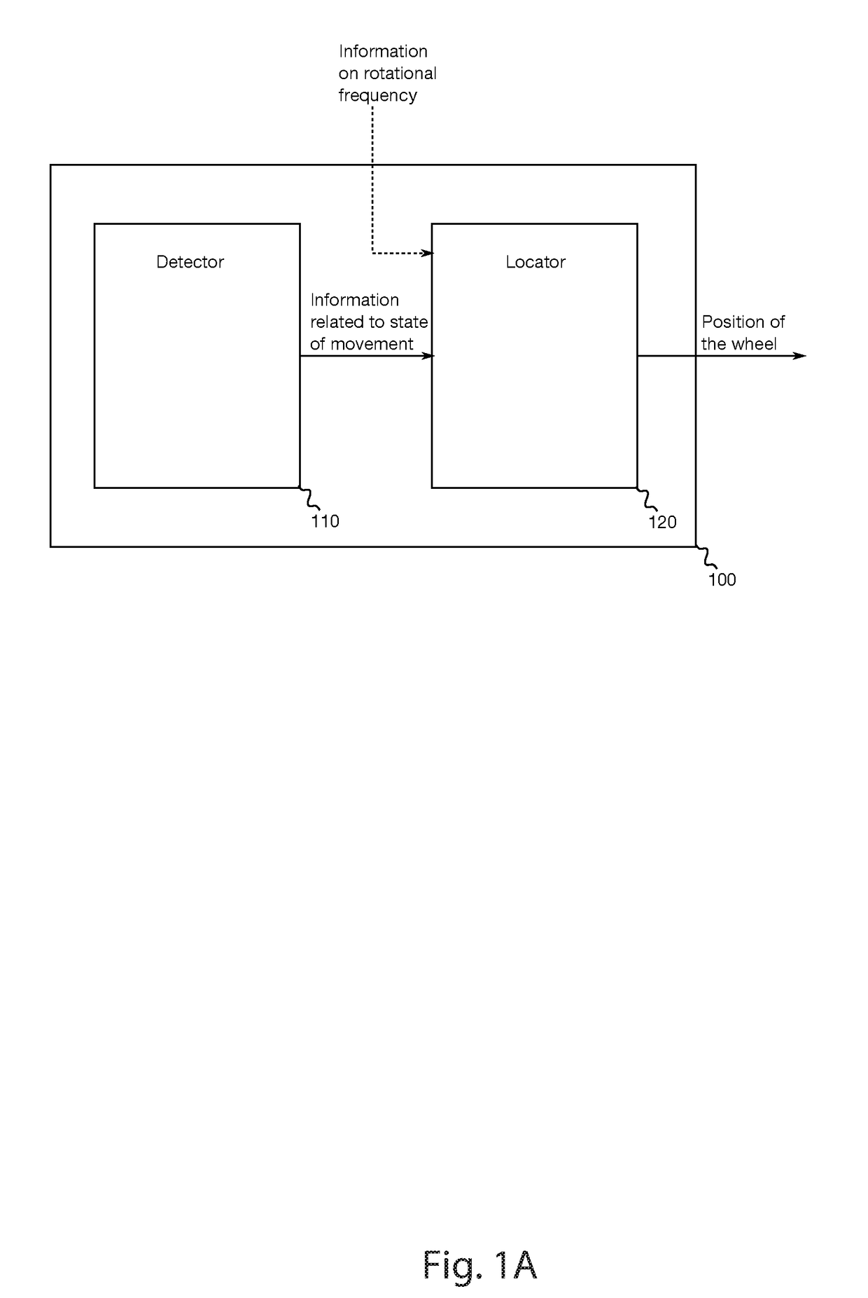
[0076]FIG. 1a shows an embodiment of a system 100 for locating a position of a wheel on a vehicle. The system 100 comprises a detector 110 for obtaining information related to a state of movement of the vehicle, and a locator 120 for determining the position of the wheel based on the information related to the state of movement of the vehicle. The information on the state of movement may correspond to information related to a steering angle of the vehicle. The locator 120 may be operable to further use information on a rotational frequency of the wheel to determine the position of the wheel based on the information related to the state of movement or to the steering angle of the vehicle as indicated b...


PUM


Abstract

A device, a system, a method and a computer program for locating a plurality of positions of a plurality of wheels on a vehicle disclosed. The device includes an input to obtain information related to a position of one wheel from the plurality of wheels, and a detector to obtain information related to rotational frequencies of the one wheel and of at least one other wheel of the plurality of wheels. The device further includes a locator coupled to the input and to the detector. The locator is configured to determine information related to the position of the at least one other wheel based on the information related to the position of the one wheel and based on the information related to the rotational frequencies. Additionally or alternatively, the device may include one or more inputs to obtain information related to rotational frequencies of the plurality of wheels and information related to accelerations at the plurality of wheels. The device may further include a locator coupled to the one or more inputs. The locator is configured to determine the plurality of positions of the plurality of wheels based on the information related to the rotational frequencies of the plurality of wheels and based on the information related to the accelerations at the plurality of wheels.

Description

REFERENCE TO RELATED APPLICATION[0001]This application is a divisional of U.S. application Ser. No. 14 / 982,721 filed on Dec. 29, 2015, which is a continuation in part of U.S. application Ser. No. 13 / 969,742 filed on Aug. 19, 2013, which claims priority to U.S. Provisional Application No. 61 / 693,509 filed on Aug. 27, 2012, the contents of which are incorporated by reference in their entirety.FIELD[0002]Embodiments of the present disclosure relate to a device, a system, a method and a computer program for locating a plurality of positions of a plurality of wheels on a vehicle.BACKGROUND[0003]Tire Pressure Monitoring Systems (TPMS) are designed to monitor the air pressure inside of pneumatic tires on various types of vehicles. Therefore pressure sensors are used in the tires and the system may report the tire pressure information to the driver of the vehicle. Wireless transmission can be used to transmit information on the pressure data to a centralized receiver component in the vehicl...

Claims


Application Information

Patent Timeline
Patent Type & Authority Applications(United States)
IPC IPC(8): B60C23/04G01B7/30B60C19/00
CPCB60C23/0488B60C2019/004B60C23/0416B60C19/00G01B7/30
Inventor PEINE, ANDREKANDLER, MICHAELBODINI, EMANUELE BRUNO
Owner INFINEON TECH AG
Learn More