Patient isolation unit

a technology for isolation units and patients, applied in auxillary pretreatment, cleaning using liquids, separation processes, etc., can solve the problems of inconvenient storage, difficult handling of units, and inability to meet the needs of patients, so as to achieve convenient transportation and storage, and facilitate maintenance. the effect of easy and economical maintenan

Inactive Publication Date: 2005-11-22
SANKI ENG CO LTD
View PDF18 Cites 45 Cited by
  • Summary
  • Abstract
  • Description
  • Claims
  • Application Information

AI Technical Summary

Benefits of technology

[0015]Germs and bacteria in the air discharged from the envelope are partly captured by the filter means and partly stick to the inner surface of the exhauster upstream of the filter means, and are killed by the sterilizing means. This prevents the germs and bacteria from being discharged to outside from the exhauster. Moreover, the germs and bacteria do not leak out from the envelope since the inside of the bottomed envelope is kept under negative pressure.
[0016]These features enable a patient with a contagious disease to be treated in a safe environment and an operator to safely exchange the filter means without being infected.
[0017]Since the germs and bacteria sticking to the filter means in the exhauster can be killed by the sterilizing means, the filter means does not need to be discarded every time the spent envelope is incinerated after completed use of the isolation unit. As a result, the filter means lasts for a longer period to be economical.
[0018]Furthermore, since the frame body is foldable and / or capable of being disassembled, it can be easily transported and stored in a smaller space and therefore is easy and economical in maintenance.

Problems solved by technology

In recent years, in-hospital infection caused, for example, by bacilli from tuberculous patients has been a major problem.
Furthermore, no specific consideration is given for convenient transportation and storage of the unit.
Furthermore, since the unit needs to be transported in a state of being fully assembled, the unit is hard to handle and requires a larger space for storage.
However, no specific consideration is given to convenience in transportation of the frame body in the folded state.
Nevertheless, the former is still inconvenient in terms of its need to transport the frame body in a state of being lifted up.

Method used


Image

  • Patient isolation unit
  • Patient isolation unit
  • Patient isolation unit

Examples


Embodiment Construction

[0068]An embodiment of the present invention will be described in conjunction with the accompanying drawings.

[0069]FIGS. 1 to 31 show an embodiment of a patient isolation unit according to the present invention.

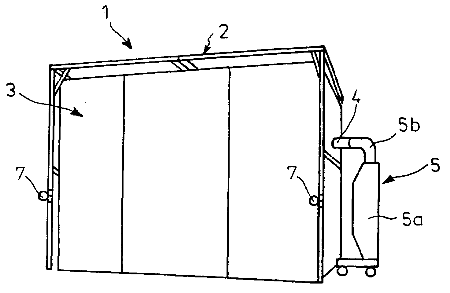
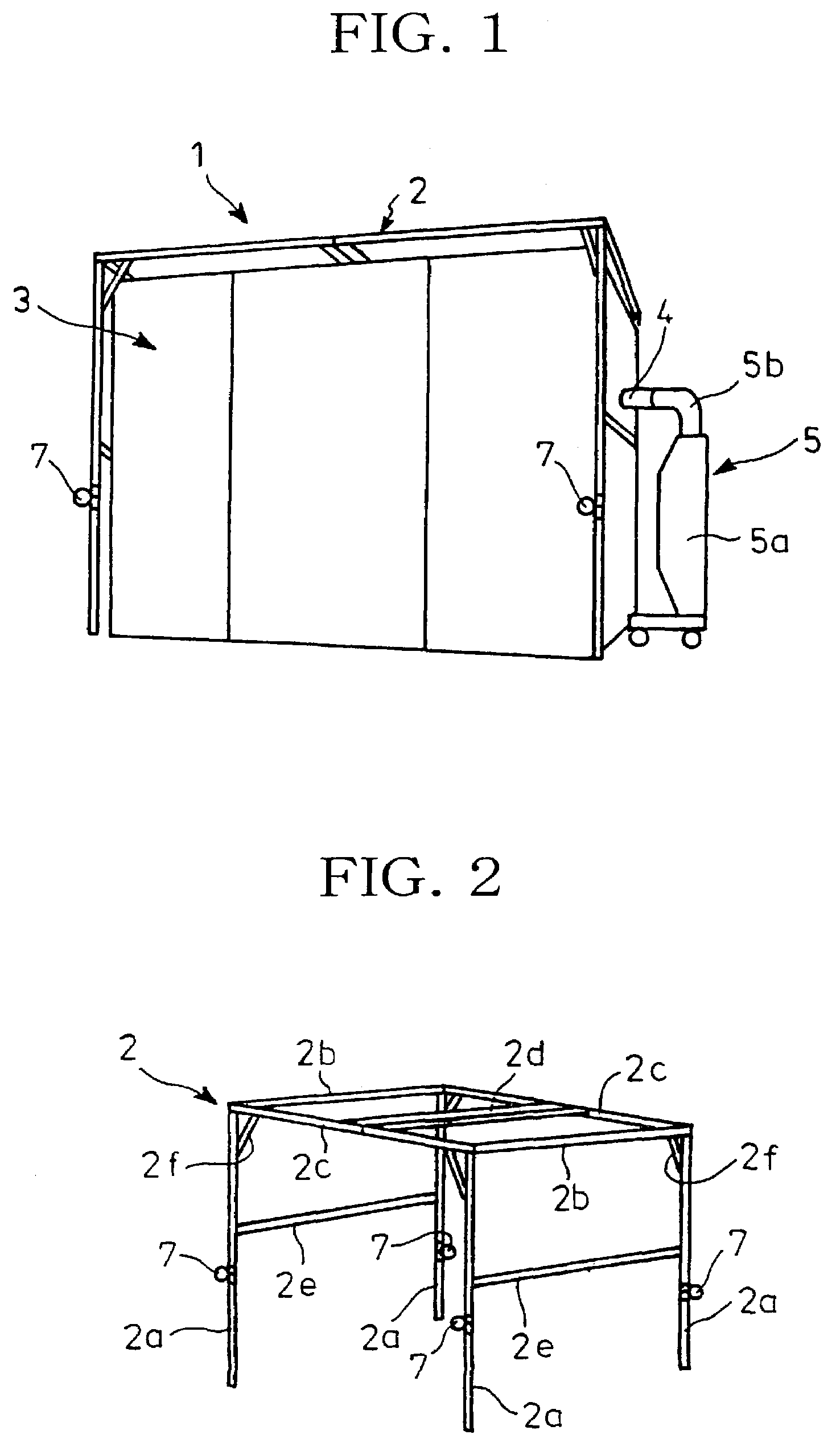
[0070]In FIG. 1, a patient isolation unit 1 comprises a frame body 2 assembled, a flexible envelope 3 detachably attached to the frame body 2 and an exhauster 5 connected to the envelope 3 through an exhaust duct 4.

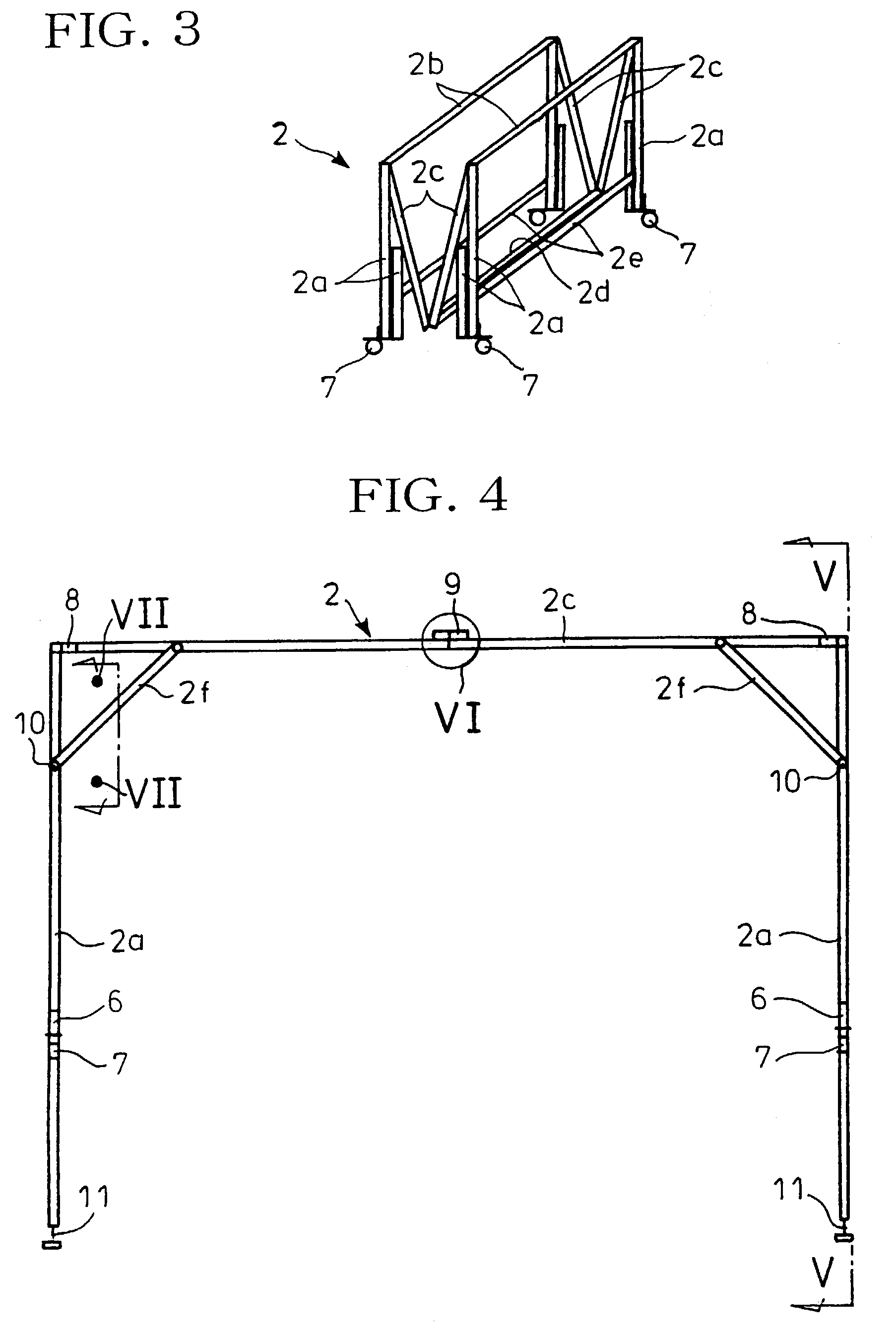
[0071]The frame body 2 is made of aluminum and is provided with four pillars 2a each constituted by upper and lower pillar portions which are foldably interconnected by a hinge 6 as shown, for example, in FIG. 8. The upper pillar portion is provided, at its lower end, with a caster-type wheel 7. Interconnection of the upper and lower pillar portions by the hinge 6 is supported by fold-preventive means (see FIG. 34) such that the pillar 2a is not unintentionally folded in use of the patient isolation unit 1.

[0072]The pillars 2a are connected at their upper ends with...


PUM

PropertyMeasurementUnit
flammable flexibleaaaaaaaaaa
flexibleaaaaaaaaaa
pressureaaaaaaaaaa

Abstract

A patient isolation unit including a foldable frame body, a flexible envelope made of a flammable resin sheet which can be attached to the assembled frame body, and an exhauster to discharge or exhaust the air from the envelope. The exhauster includes a UV lamp, an HEPA filter, and a blower.

Description

CROSS-REFERENCE TO RELATED APPLICATIONS[0001]This application is related to and claims priority, under 35 U.S.C. § 119, from Japanese Patent Application No. 2002-307051, filed in the Japanese Patent Office on Oct. 22, 2002, the entire contents of which is hereby incorporated by reference herein.BACKGROUND OF THE INVENTION[0002]1. Field of the Invention[0003]The present invention relates to a patient isolation unit for temporarily isolating a patient with contagia such as tubercle bacilli for having treatment. More particularly, the present invention relates to an economical patient isolation unit of the kind mentioned which eliminates the need to discard filter means every time an envelope is discarded after completed use of the isolation unit and which can be easily transported and stored in a smaller space.[0004]2. Discussion of Background[0005]In recent years, in-hospital infection caused, for example, by bacilli from tuberculous patients has been a major problem. It is desirable...

Claims


Application Information

Patent Timeline
Patent Type & Authority Patents(United States)
IPC IPC(8): B01D46/42A61L9/20A61G10/00B01D46/00
CPCA61G10/005B01D46/0002B01D46/0016B01D2279/65Y10S55/18Y10S55/46Y10S55/29B01L1/04A61G10/00
Inventor YACHI, TAKASHITAKAGI, SABUROIIJIMA, KAZUAKIIDE, TAKEYA
Owner SANKI ENG CO LTD
Why Eureka
Try Eureka