Slingshot

a slingshot and fork technology, applied in the field of slingshot, can solve the problems of lack of repeatability in using the slingshot, and achieve the effect of inhibiting the movement of the fork portion

Inactive Publication Date: 2005-11-29
LEE ALDRIC KUO CHUN
View PDF7 Cites 31 Cited by
  • Summary
  • Abstract
  • Description
  • Claims
  • Application Information

AI Technical Summary

Benefits of technology

[0008]Further, in accordance with the present invention, there is provided a slingshot body for use with an elastic member in slinging a projectile. A fork portion to which the elastic member is to be attached and a gripping portion to be grasped by a user of the slingshot body are provided. A stabilizing member is used to inhibit undesired movement of said fork portion.
[0009]Further, in accordance with the present invention, there is provided a slingshot body for use with an elastic member in slinging a projectile. A fork portion to which the elastic member is to be attached and a gripping portion to be grasped by a user of the slingshot body. A mounting apparatus pivotally connects the fork portion and the gripping portion to one another. The mounting apparatus includes a connecting portion for connecting the fork portion and the gripping portion to one another by a predetermined distance sufficient to overcome friction forces created in the mounting apparatus when drawing the elastic member to a shooting position.
[0010]Further, in accordance with the present invention, there is provided a slingshot body for use with an elastic member in slinging a projectile. A fork portion to which the elastic member is to be attached and a gripping portion to be grasped by a user of the slingshot body. A pivotal connecting apparatus pivotally connects the elastic member to the fork portion. The pivotal connecting apparatus includes an elongated connecting member pivotally connected in close proximity to an outboard end of the fork portion and the elongated connecting member has a length sufficient to overcome friction forces created when drawing the elastic member to a shooting position.

Problems solved by technology

Further, after the projectile is released, the user may change his or her grip on the slingshot body that will effect the positioning of the forked portion relative to the release point and result in a lack of repeatability in using the slingshot.

Method used


Image

  • Slingshot
  • Slingshot
  • Slingshot

Examples


Embodiment Construction

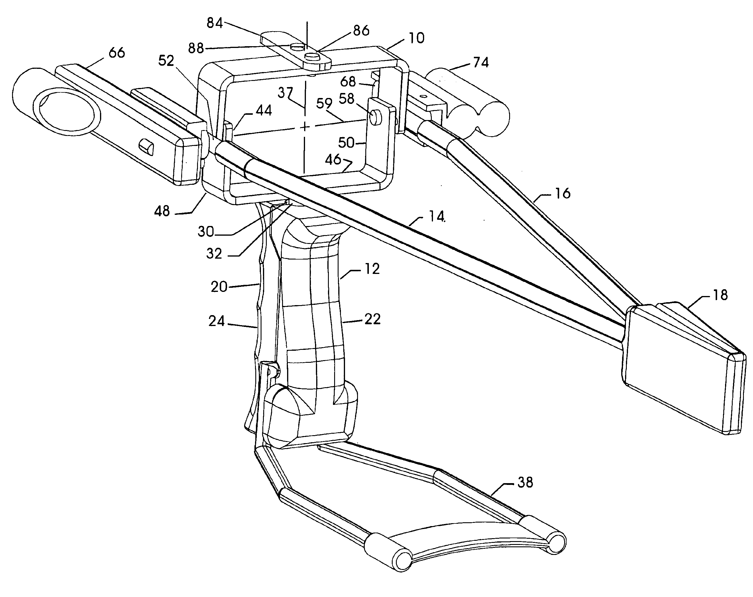
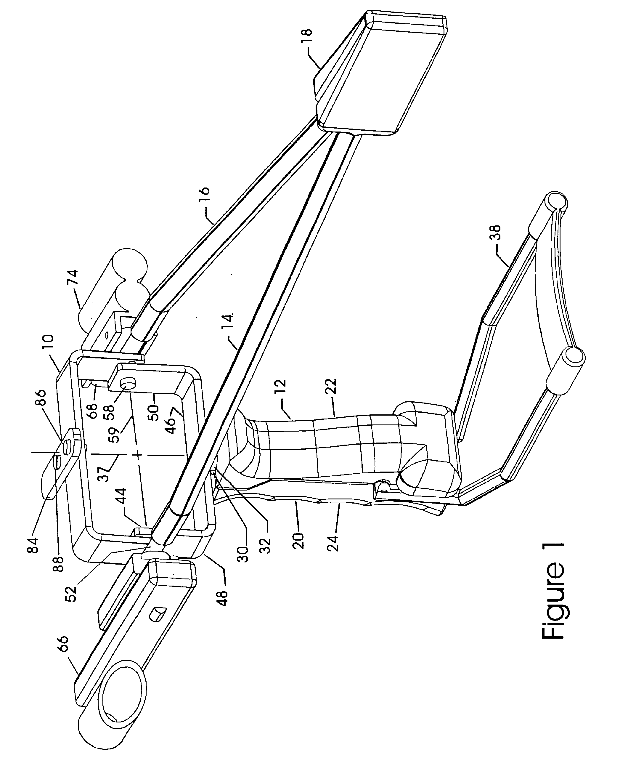
[0021]Turning now to the drawing, there is shown a slingshot 10 with a slingshot body 12, first and second conventional elastic members 14 and 16, respectively, and a conventional pouch 18 for supporting a projectile (not shown).

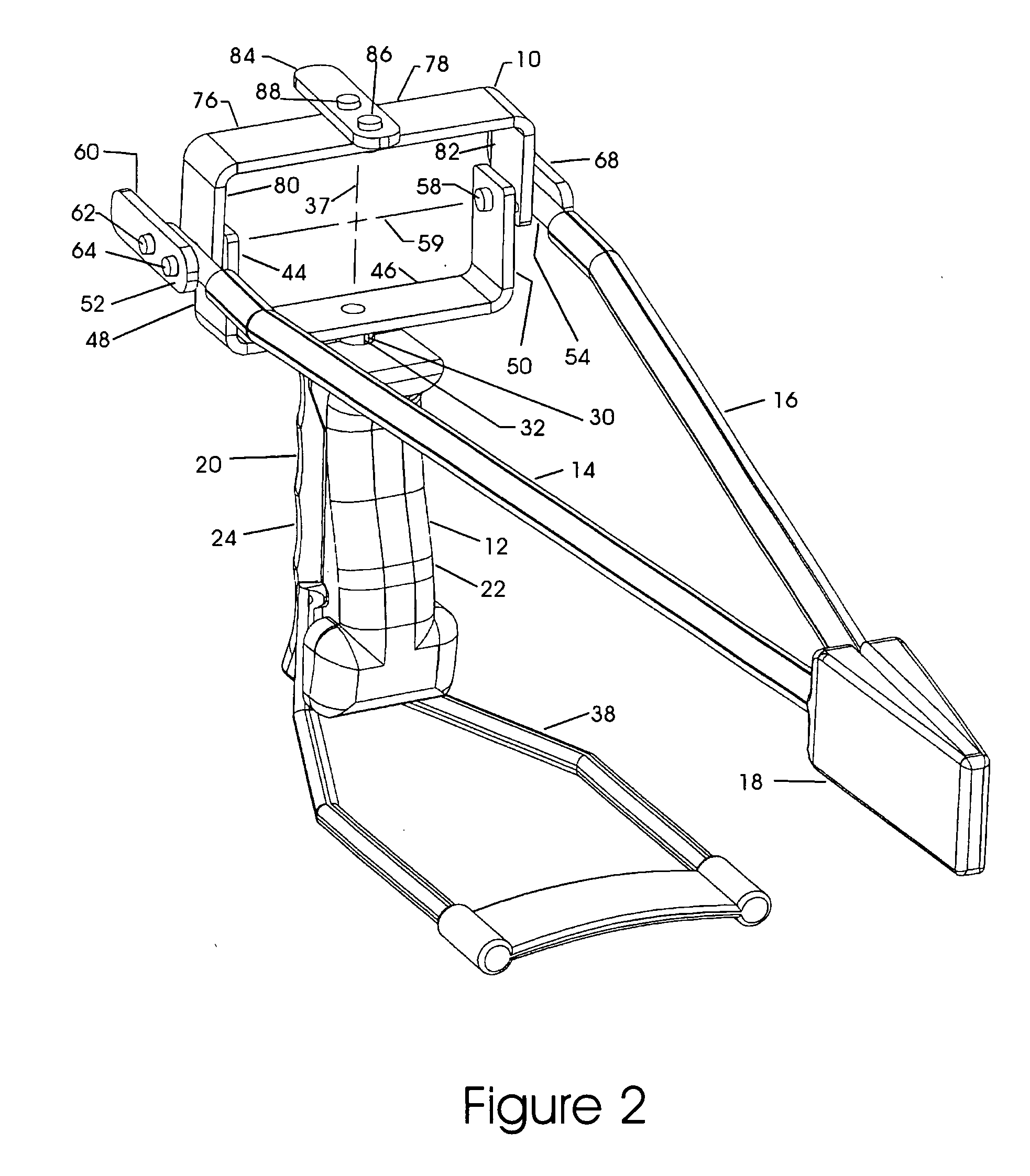
[0022]As best seen in FIG. 2, slingshot body 12 has a gripping portion 20 to be grasped by a user of slingshot 10 and is elongated with a length sufficient to be engaged and gripped by a hand of the user of slingshot 10. Gripping portion 20 is constructed with a user side portion 22 generally facing toward the user and a target side portion 24 generally facing away from the user. User side portion 22 and target side portion 24 are constructed to complementary engage one another and form elongated gripping portion 20 when joined together in a conventional manner. User side portion 22 is constructed to generally conform to a palm of a user's hand when gripping portion 20 is held in the user's hand and target side portion 24 is constructed to form finger grips ...


PUM


Abstract

A slingshot body for use with an elastic member in slinging a projectile. A fork portion to which the elastic member is to be attached and a gripping portion to be grasped by a user of the slingshot body are provided. Mounting apparatus pivotally connects the fork portion and the gripping portion to one another to allow movement of the gripping portion within the user's hand. The mounting apparatus including a connecting portion for connecting the fork portion and the gripping portion to one another by a predetermined distance sufficient to overcome friction forces created when drawing the elastic member to a shooting position.

Description

BACKGROUND OF THE INVENTION[0001]This invention relates to a slingshot and, more particularly, to a slingshot body for use with an elastic member in slinging a projectile.[0002]Slingshots have been used for many years. Normally, a user of the slingshot wraps a pouch around a projectile, overcomes the resistance caused by elastic members connected to the arms of a forked portion of the body and moves the pouch into a projectile launching position. Unless the user holds the forked portion exactly perpendicular to a projectile release point, the elastic members may apply unequal forces to the pouch. In which event, the projectile will not fly as true a course as the user desires. Further, after the projectile is released, the user may change his or her grip on the slingshot body that will effect the positioning of the forked portion relative to the release point and result in a lack of repeatability in using the slingshot. In order to eliminate these problems, an improved slingshot bod...

Claims


Application Information

Patent Timeline
Patent Type & Authority Patents(United States)
IPC IPC(8): F41B3/02
CPCF41B3/02
Inventor LEE, ALDRIC KUO-CHUN
Owner LEE ALDRIC KUO CHUN
Why Eureka
Try Eureka