Turbine airfoil cooling flow particle separator

a technology of airfoil and separator, which is applied in the direction of propulsive elements, marine propulsion, vessel construction, etc., can solve the problems of airfoil burning, airfoil oxidation, and small features that are prone to dirt particles and oxidation

Active Publication Date: 2005-11-29
RTX CORP
View PDF20 Cites 45 Cited by
  • Summary
  • Abstract
  • Description
  • Claims
  • Application Information

AI Technical Summary

Benefits of technology

[0018]It is apparent that there has been provided in accordance with the present invention an inertial particle separator for cooling air provided to turbine blades which fully satisfies the objects, means, and advantages set forth previously herein. While the present invention has been described in the context of specific embodiments thereof, other alternatives, modifications, and variations will become apparent to those skilled in the art having read the foregoing description. Accordingly, it is intended to embrace those alternatives, modifications, and variations as fall within the broad scope of the appended claims.

Problems solved by technology

Unfortunately, these small features are prone to plugging by dirt particulates.
By clogging the cooling features, the dirt particulates result in the burning and oxidation of the airfoils.

Method used


Image

  • Turbine airfoil cooling flow particle separator
  • Turbine airfoil cooling flow particle separator
  • Turbine airfoil cooling flow particle separator

Examples


Embodiment Construction

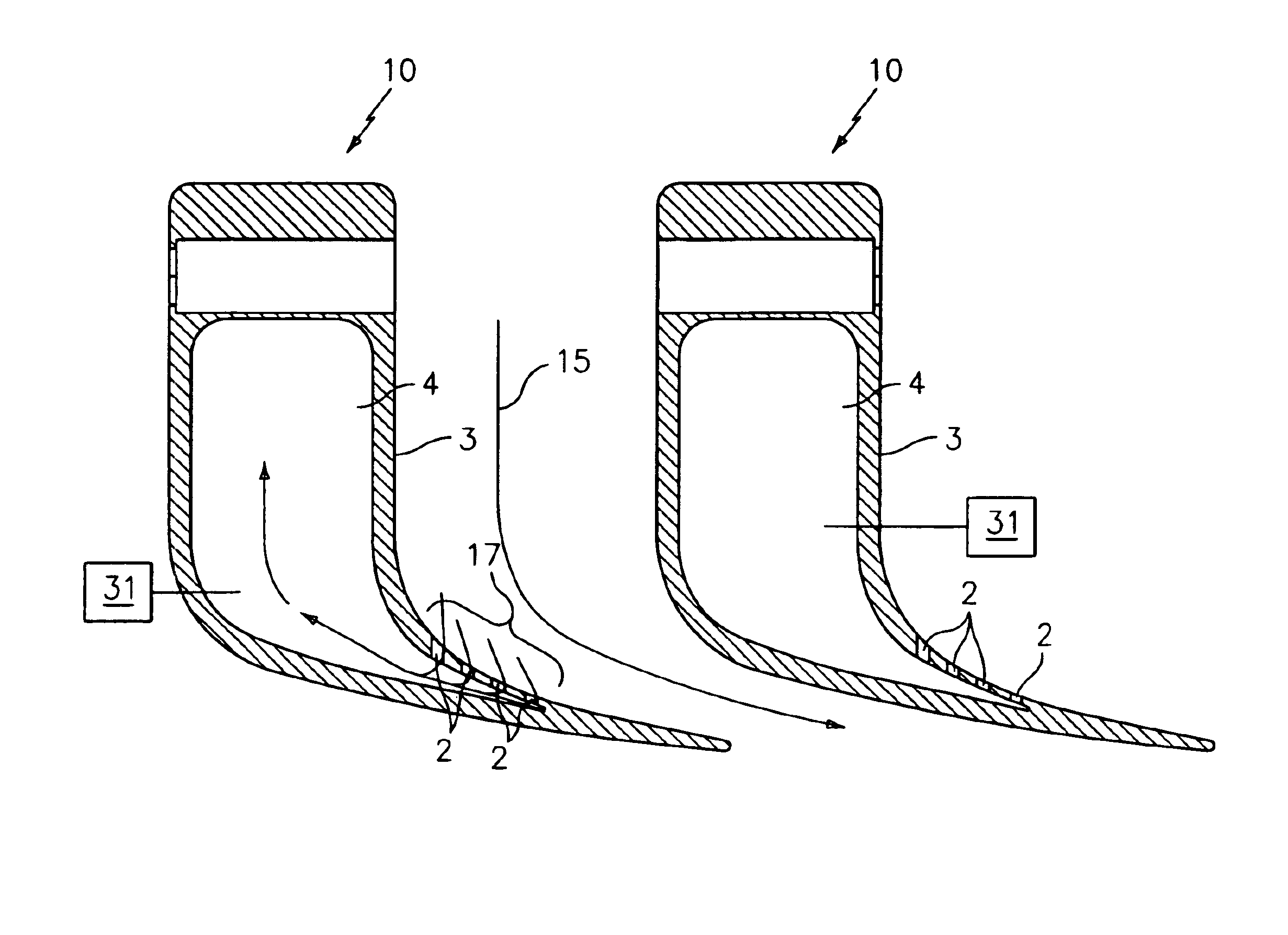
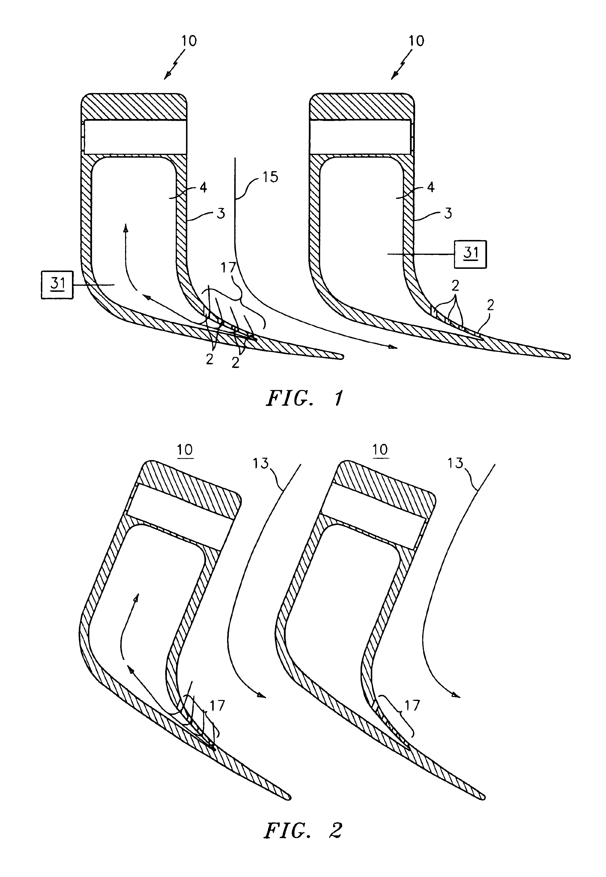
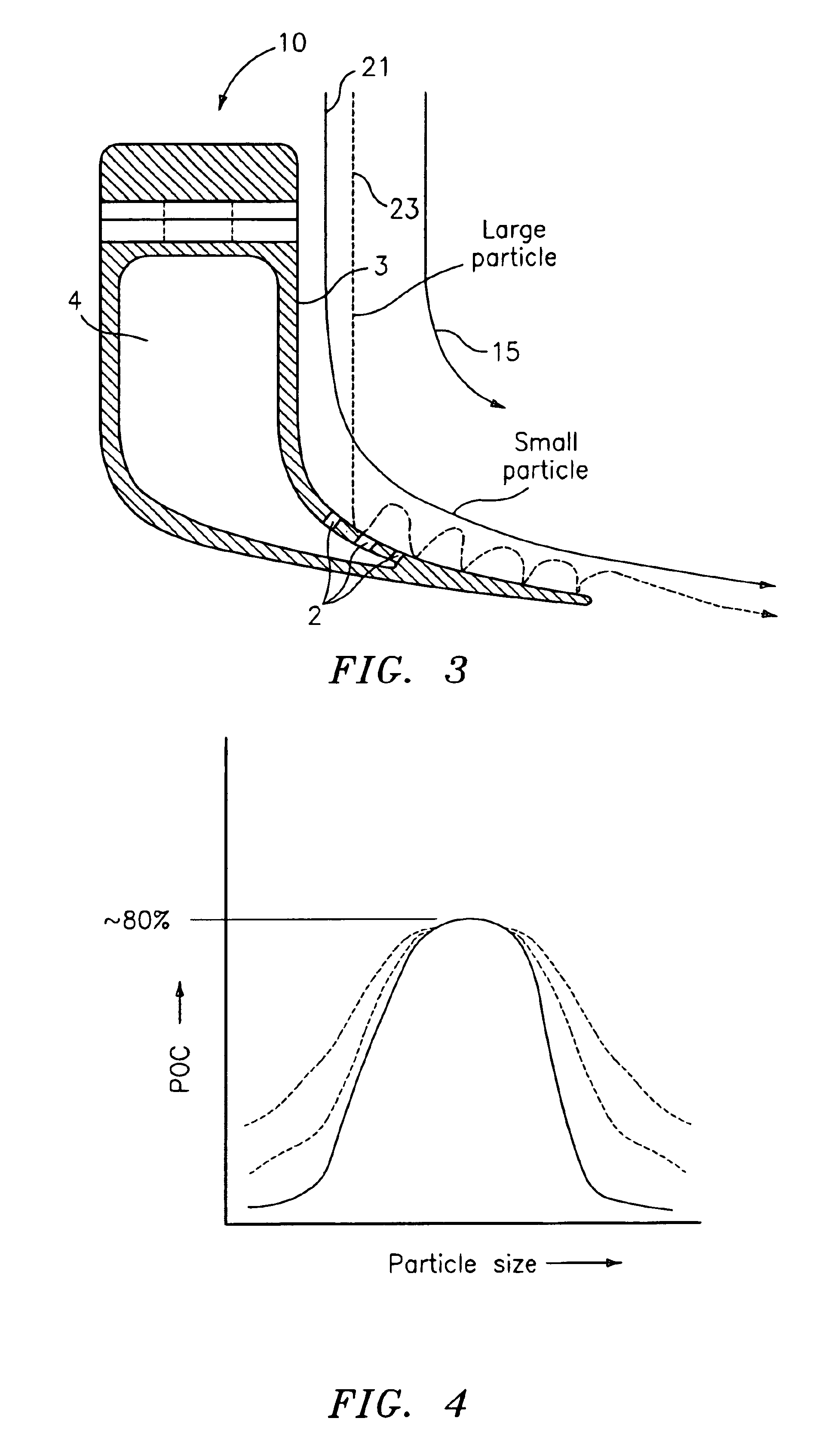
[0014]It is therefore the primary objective of the present invention to provide an inertial particle separator for cooling air provided to turbine blades. The object of the present invention is primarily achieved by adding one or more slots, or openings, to existing turning vanes of a size and orientation sufficient to capture and evacuate particles present within the airflow. As will be described more fully below, particles present in the airflow tend to travel along the pressure side of turning vanes. Depending on the size and the mass of the particles contained within the airflow, the inertia of the particles may be used to capture the particles as they impact upon the pressure side of the turning vane. By including a series of openings or slots in the wall of the airfoil, it is possible to capture a considerable percentage of particles as the airflow moves through the turning vanes.

[0015]With reference to FIG. 1 there is illustrated a plurality of turning vanes 10 of the present...


PUM


Abstract

A vane assembly for a turbine engine comprising a plurality of vanes each comprising a pressure side wherein the pressure side of at least one of the plurality of vanes comprises at least one opening extending through the pressure side into an interior portion of the at least one of the plurality of vanes.

Description

U.S. GOVERNMENT RIGHTS[0001]The invention was made with U.S. Government support under contract F33615-97-C-2779 awarded by the U.S. Air Force. The U.S. Government has certain rights in the invention.BACKGROUND OF THE INVENTION[0002](1) Field of the Invention[0003]The present invention relates an inertial particle separator for cooling air provided to turbine blades.[0004](2) Description of the Related Art[0005]Gas turbine engine design and construction requires ever increasing efficiency and performance. In order to achieve such increased efficiency and performance, often times the combustion component of the engine is modified such that exit temperatures are elevated. However, turbine airfoil temperature capability must be raised in such instances owing to the need for durability. In response to this need, various methods have been introduced to improve the cooling technology employed on turbine blades. These cooling schemes employ small holes and passages for cooling air flow. The...

Claims


Application Information

Patent Timeline
Patent Type & Authority Patents(United States)
IPC IPC(8): F01D25/00F01D5/18F01D25/32F02C7/052
CPCF01D5/081F01D25/32F01D5/18F05D2260/607
Inventor HUDSON, ERIC A.
Owner RTX CORP
Why Eureka
Try Eureka